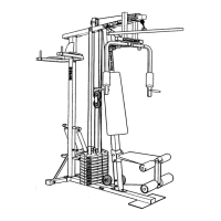
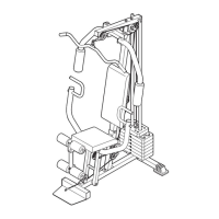
CABLE DIAGRAM
The cable diagram shows the proper routing of the
Long Cable (80). Use the diagram to make sure that
the cable has been assembled correctly. If the cable
has not been correctly routed, the resistance system
will not function properly and damage may occur. The
numbers show the correct route for the cable.
7
4
5
6
1
2
Long Cable (80)
3
16 5
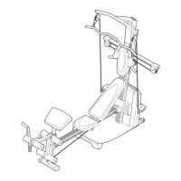
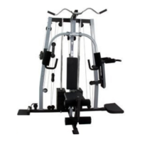
USING THE REMOVABLE CROSSBOWS
The Removable Crossbows (36, 67) can be used to
exercise apart from the resistance system, as shown in
the video or on the exercise guide. To remove a
Crossbow, pull it out of the Crossbow Spacer (35).
To replace the Removable Crossbows (36, 67), slide
them into the Crossbow Spacer (35) from the side
shown, so that the arrows on the rings point toward
the Crossbow Spacer. Make sure the rings are
pushed against the Crossbow Spacer.
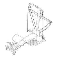
ADJUSTING THE LEG DEVELOPER
To adjust the height of the Leg Developer (19),
remove the Bench Knob (42) from the Front Leg (6).
Align the hole in the Leg Developer with one of the
holes in the Front Leg. Retighten the Knob into the
Front Leg and Leg Developer.
35
19
42
6
5
36
67
Rings
Before beginning assembly, carefully read the
following information and instructions:
• Assembly requires two persons.
• Place all parts in a cleared area and remove the
packing materials. Do not dispose of the packing
materials until assembly is completed.
• For help identifying small parts, use the PART
IDENTIFICATION CHART. Note: Some small
parts may have been pre-attached for shipping. If
a part is not in the parts bag, check to see if it
has been pre-attached.
• Tighten all parts as you assemble them, unless
instructed to do otherwise.
• As you assemble the resistance system, make
sure all parts are oriented as shown in the draw-
ings.
The included hex keys and the following
tools (not included) are required for assembly:
• two adjustable spanners
• one rubber mallet
• one standard screwdriver
• one Phillips screwdriver
• lubricant, such as grease or petroleum jelly,
and soapy water.
Assembly will be more convenient if you have a
socket set, a set of open-end or closed-end span-
ners, or a set of ratchet spanners.
Make Things Easier for Yourself
This manual is designed to ensure that the resist-
ance system can be assembled successfully by
most people. However, it is important to realise
that the versatile resistance system has many
parts and that the assembly process will take
time. Most people find that by setting aside plenty
of time, assembly will go smoothly.
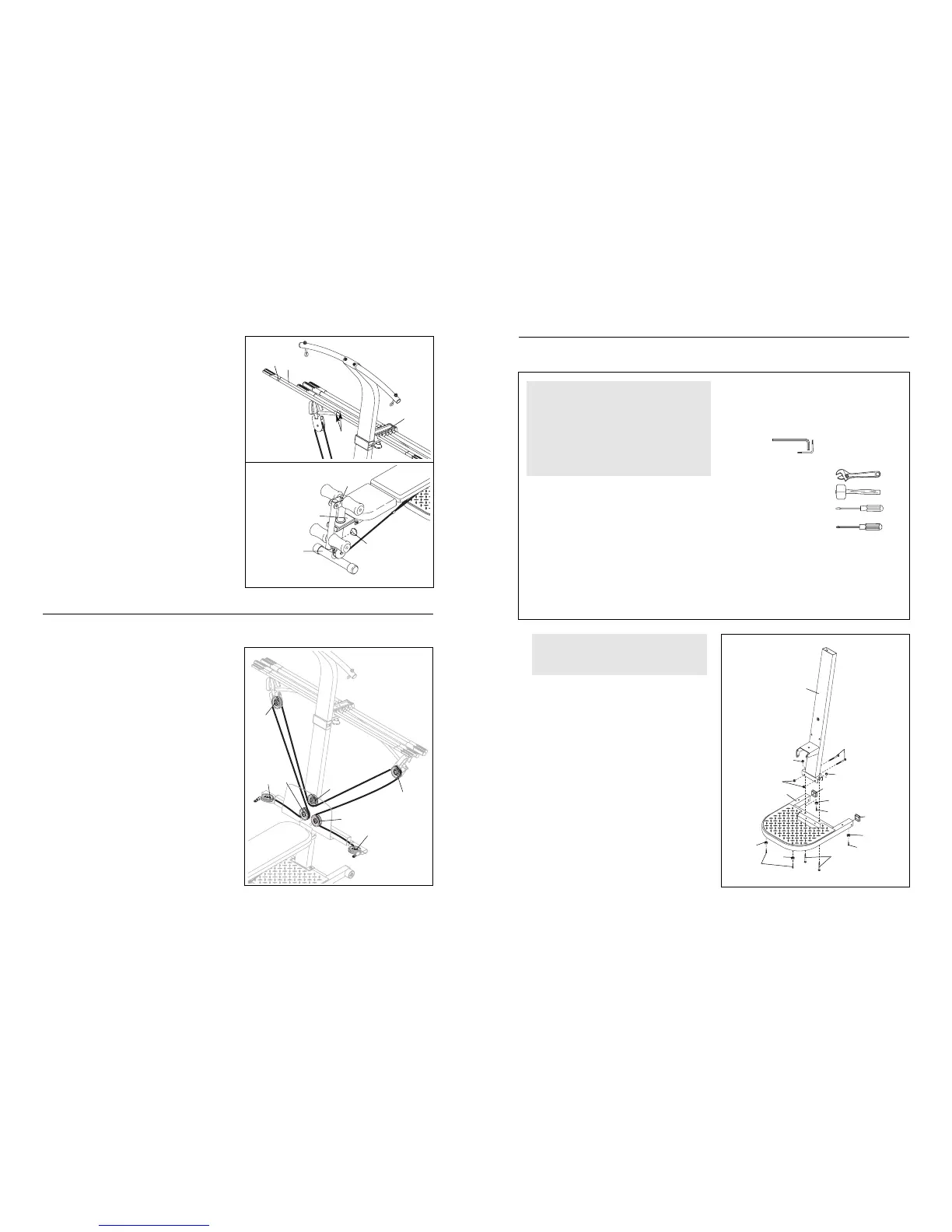
ASSEMBLY
1
1.
Press two 50mm Square Inner Caps (98) into the
Base (1).
Attach two Plastic Feet (53) and two Large Plastic
Feet (102) to the Base (1) with four M4 x 16mm
Screws (62).
Attach the Upright (3) to the Base (1) with two
M10 x 66mm Carriage Bolts (83), two M10 x
72mm Bolts (64), and four M10 Nylon Locknuts
(76) as shown. Note: This step will be easier to
complete if the Upright and Base are tipped
on their sides.
Before beginning assembly, make sure that
you have read and understand the informa-
tion in the box above.
76
76
76
64
3
62
1
53
53
62
102
62
102
98
98
83