75
156
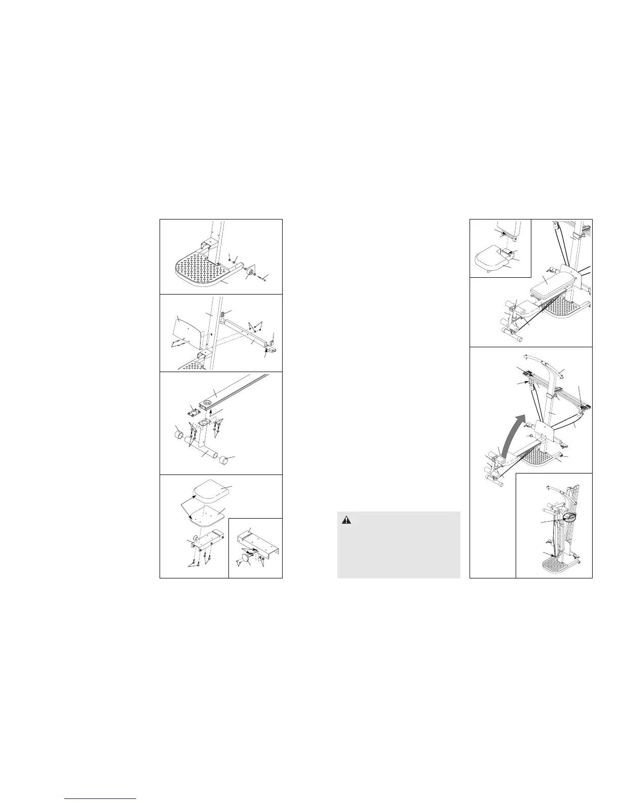
2. Attach a Wheel (31) to the outside of the Base (1)
with an M10 x 108mm Bolt (81), three M10
Washers (75), and an M10 Nylon Locknut (76).
Do not overtighten the Nylon Locknut; the
Wheel must be able to turn easily.
Attach the other Wheel (not shown) in the
same manner.
2
1
30
31
1
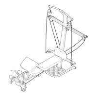
Crossbows
6
7
3
43
44
“U”-Channel
“U”-Channel
80
10
13
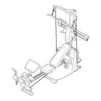
STORING THE RESISTANCE SYSTEM
To store the resistance system, slide the ends of the
Leg Lever Cable (32) onto the Hook (104). Be sure
the Seat (13) is in the position closest to the Front
Leg (6) (see ADJUSTING THE SEAT on page 13).
Next, remove the Storage Knob (30) from the Upright
(3). Lift the Front Leg toward the Lat Tower Crossbar
(10), and tighten the Storage Knob into the side of
the Upright and the Bench Rail. Remove all of the
crossbows from the “U”-channels on the 10-pound
centre Crossbow (44) (see ADJUSTING THE
RESISTANCE on page 14). Finally, loosen the
Fulcrum Knob (43) and pull it out as far as it will go.
Turn the crossbow assembly vertically and engage
the Fulcrum Knob into the fulcrum on the Lat Tower
(4). Note: Storing the crossbows vertically will
prolong the life of the crossbows.
To move the resistance system, place the toe of your
shoe on the end of the Base (1) and hold the resist-
ance system in the indicated area. Tilt the resistance
system back onto the Wheels (31) and roll it to the
new location. Be careful not to let the Front Leg (6)
or Leg Lever (7) pinch your hands when you tilt
the system back.
WARNING: Be sure that all of the
crossbows are removed from the “U”-channels
before moving the crossbow assembly to the
stored position.
Make sure that the crossbow assembly is in
the horizontal position and that the Storage
Knob (30) is in place and fully tightened each
time the resistance system is used.
32
31
75
76
75
81
3. Press a 38mm x 64mm Inner Cap (41) into each
end of the Cross Tube (11).
Orient the Cross Tube (11) as shown, with the
welded tubes at the bottom. Attach the Foot Plate
(23) and the Cross Tube to the Upright (3) with
two M10 x 143mm Carriage Bolts (73), two M10
Washers (75), and two M10 Nuts (47). Do not
insert a bolt into the top hole in the Foot Plate
yet.
3
4
41
3
73
41
Welded
Tube
11
47
23
5. See the inset drawing. Snap the Seat Knob (45)
into the Seat Carriage (12) and attach it with two
M6 x 16mm Screws (82) and two M6 Black Nylon
Locknuts (69). Make sure the slot in the Knob
is aligned with the slot in the Seat Carriage.
Orient the Seat (13) and Seat Backing (9) as
shown. Attach the Seat and Seat Backing to the
Seat Carriage (12) with four M6 x 16mm Screws
(82).
4. Press two 57mm Round Outer Caps (27) onto the
ends of the Front Leg (6).
Orient the Bench Rail (5) as shown. Slide the Rail
Bracket (105) into the indicated end of the Bench
Rail, and align the holes in the Bracket with the
holes in the Bench Rail.
Orient the Front Leg (6) as shown. Attach the
Front Leg to the Bench Rail (5) with the Rail
Bracket (105), four M8 x 25mm Button Screws
(46), and four M8 Split Washers (52).
5
14
15
12
13
Rod
Slot
5
12
19
7
3
ADJUSTING THE BACKREST
The Backrest (14) can be used in a level position or
one of three inclined positions. To use the Backrest in a
level position, secure the Seat Carriage (12) at the hole
in the Bench Rail (5) closest to the Leg Developer (19)
(see ADJUSTING THE SEAT on page 13).
To use the Backrest (14) in an inclined position,
secure the Seat Carriage (12) at one of the three
adjustment holes on the Upright (3) side of the Bench
Rail (5). Rest the Backrest against the Upright (3).
For row exercises and for using the Leg Lever (7),
remove the Backrest (14) from the Seat Carriage
(12). Hold the Backrest vertically over the Seat (13)
and lift the rod out of the slot in the Seat Carriage
(see the inset drawing). To use the Leg Lever (7),
secure the Seat Carriage (12) at the second hole
from the Leg Developer.
Stored Position
104
Hold in
this area
5
105
Holes
6
46
52
52
46
27
27
13
9
Round
End
Slot
12
12
45
69
82
82
82