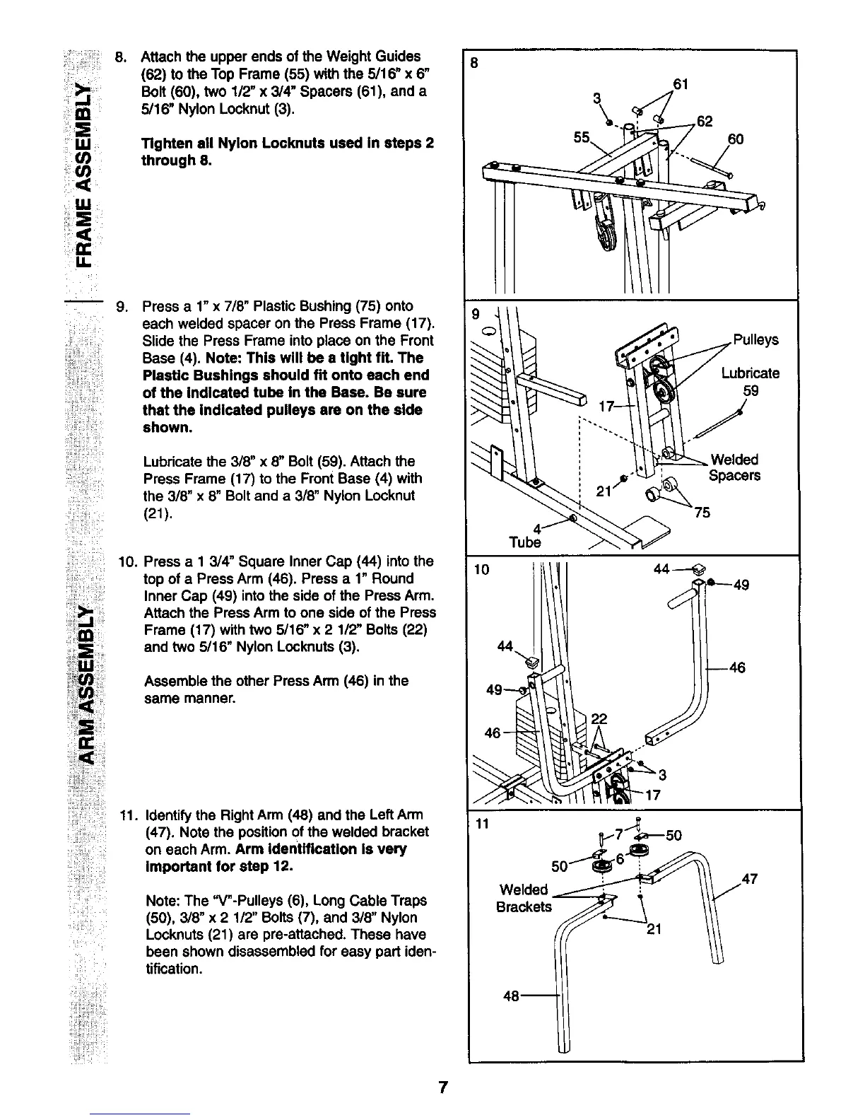
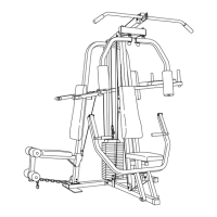
:: 8. Attach the upper ends of the Weight Guides
(62) to the Top Frame (55) with the 5/16" x 6"
Bolt (60), two 1/2" x 3/4" Spacers (61), and a
5/16" Nylon Locknut (3).
i ¸ Ul
Tighten all Nylon Locknute used In steps 2
through 6.
,
i!!!iiiiiiii!iii!!il110
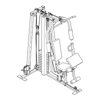
Press a 1" x 7/8" Plastic Bushing (75) onto
each welded spacer on the Press Frame (17).
Slide the Press Frame into place on the Front
Base (4). Note: This will be a fight fit. The
Plastic Bushings should fit onto each end
of the indicated tube in the Base. Be sure
that the indicated pulleys are on the side
shown.
Lubricate the 3/8" x 8" Bolt (59). Attach the
Press Frame (17) to the Front Base (4) with
the 3/8" x 8" Bolt and a 3/8" Nylon Locknut
(21).
Press a I 3/4" Square Inner Cap (44) intothe
top of a Press Arm (46). Press a 1" Round
Inner Cap (49) into the side of the Press Arm.
Attach the Press Arm to one side of the Press
Frame (17) with two 5116" x 2 1/2" Bolts (22)
and two 5116"Nylon Locknuts (3).
Assemble the other Press Arm (46) in the
same manner.
ii!iiiiiiiiii_ili_i;iiiiii!_
i!!iiiiiiii!!iiliil11.
iiiiliili
ii ¸
Identify the Right Arm (48) and the Left Arm
(47). Note the position Of the welded bracket
on each Arm. Arm Identification Is very
Important for step 12.
Note: The "V"-Pulleys (6), Long Cable Traps
(50), 3/8" x 2 1/2" Bolts (7), and 3/8" Nylon
Locknuts (21) are pre-attached. These have
been shown disassembled for easy part iden-
tification.
i;!;i_i!i:ii;iii!
8
61
3 . ,
Tube
10
11
_7_-_50
We,ded // 47
Brackets_ '_21
7