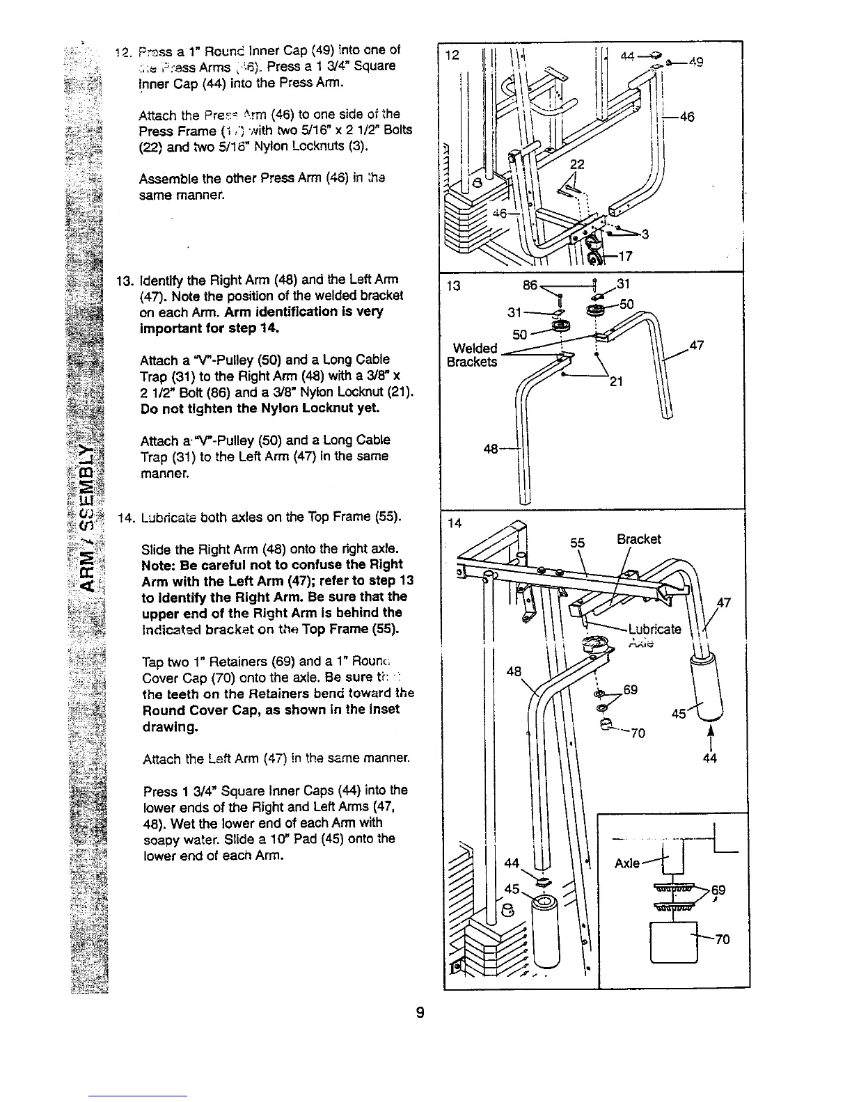
" _ !2. Press a 1" Round Inner Cap (49) into one of
....= ,_:_ss Arms, -6;. Press a 1 3/4" Square
!nner Cap (44) into the Press Arm.
Attach the Pre_ _.rm (46) to one side o_the
Press Frame (i ,') with two 5/16" x 2 1/2" Bolts
(22) and two 5/16" Nylon Locknuts (3).
Assemble the other Press Arm (46) in :ha
same manner.
13.
Identify the Right Arm (48) and the Left Arm
(47). Note the position of the welded bracket
on each Arm. Arm identification is very
important for step 14.
Attach a "V"-Pulley (50) and a Long Cable
Trap (31) to the Right Arm (48) with a 3/8" x
2 1/2' Bolt (86) and a 3/8" Nylon Locknut (21).
Do not tighten the Nylon Locknut yet.
Attach a."V"-Pulley (50) and a Long Cable
Trap (31) to the Left Arm (47) in the same
manner.
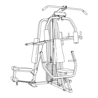
14. Lubdc-_ta both axles on the Top Frame (55).
Slide the Right Arm (48) onto the right axle.
Note: Be careful not to confuse the Right
Arm with the Left Arm (47); refer to step 13
to identify the Right Arm. Be sure that the
upper end of the Right Arm is behind the
Indtc_t_.d bracket on the Top Frame (55).
Tap two 1" Retainers (69) and a 1" Rounc;
Cover Cap (70) onto the axle. Be sure tE :-
the teeth on the Retainers bend toward the
Round Cover Cap, as shown in the inset
drawing.
Attach the Left Arm (47) in the same manner.
Press 1 3/4" Square Inner Caps (44) into the
lower ends of the Right and Left Arms (47,
48). Wet the lower end of each Arm with
soapy water. Slide a 1(7 Pad (45) onto the
lower end of each Arm.
13 86.._--_ 31
Welded /L :
7
48--
14
I"
48
Axle1
9