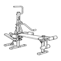
19. Remove the 3/8” Nylon Locknut (21), 3/8” x 1 3/4”
Bolt (48), and 4 1/2” Pulley (77) from one end of
the “I” Plates (78). Route the Long Cable (66)
under the Pulley and reattach the Pulley to the “I”
Plates with the Bolt and Nylon Locknut.
Refer to the inset drawing. (Note: The Wide
Swivel Bracket [71] is attached to the Top Frame
[67]; it is shown disassembled for clarity.) Lay the
Long Cable (66) over a 3 1/2” Pulley (15). Attach
the Pulley and a Cable Trap (59) to the Wide
Swivel Bracket (71) with a 3/8” x 1 3/4” Bolt (48)
and 3/8” Nylon Locknut (21). Be sure that the
Cable Trap is turned to the indicated position.
20. Wrap the Long Cable (66) down around the 3 1/2”
Pulley (15) on the left Arm (46). Tighten the 3/8”
Nylon Locknut (21) and 3/8” x 1 3/4” Bolt (not
shown). Be sure that the Cable Trap (59) is
turned to the indicated position.
21. Note: The 4 1/2” Pulley (77) shown in this step is
preattached to the Adjustment “U” Bracket (75).
Attach the Adjustment “U” Bracket (75) to the
Front Upright (42) with the 5/16” x 3 1/4” Bolt
(35), a 5/16” Flat Washer (8), and a 5/16” Nylon
Locknut (3). Thread the Nylon Locknut onto
the Bolt only two complete turns.
Remove the 3/8” x 1 3/4” Bolt (48), 3/8” Nylon
Locknut (21), and 4 1/2” Pulley (77) from the
Adjustment “U” Bracket (75). Wrap the Long
Cable (66) around the Pulley as shown. Reattach
the Pulley to the Adjustment “U” Bracket with the
Bolt and Nylon Locknut.
22. Wrap the Long Cable (66) up around the 3 1/2”
Pulley (15) on the right Arm (46). Tighten the 3/8”
x 1 3/4” Bolt (48) and 3/8” Nylon Locknut (not
shown). Be sure that the Cable Trap (59) is
turned to the indicated position.
Attach the 5/16” x 3” Bolt (17), two 5/16” Flat
Washers (8), and a 5/16” Jam Nut (2) to the indi-
cated hole in the Top Frame (67).
Slide the end of the Long Cable (66) onto the
5/16” x 3” Bolt (17). Tighten another 5/16” Jam
Nut (2) onto the Bolt.
22
66
67
2
2
59
46
8
17
20
19
21
48
48
71
77
78
15
59
21
21
46
15
77
35
21
75
48
66
3
8
42
66
21
59
66
67
66
15
48
10
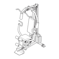
15. Attach the Wide Swivel Bracket (71) to the indi-
cated bracket on the Top Frame (67) with a 5/16”
x 3 1/4” Bolt (104) and 5/16” Nylon Locknut (3).
Do not overtighten the Nylon Locknut; the
Wide Swivel Bracket must be able to swivel
freely.
16. If the parts shown at the right have not been pre-
assembled, follow the instructions below to
assemble them.
Attach the two “I” Plates (78) to two 4 1/2” Pulleys
(77) with two 3/8” x 1 3/4” Bolts (48) and 3/8”
Nylon Locknuts (21) as shown. Do not thread
the Nylon Locknuts all the way onto the Bolts
until assembly step 24 is completed.
17. IMPORTANT: As you assemble the Long Cable
(66) and the Short Cable (not shown), refer to
page 19 of this manual to make sure that the
Cables are properly routed.
Find the end of the Long Cable (66) that does not
have a rubber ball. Insert that end of the Long
Cable up through the indicated opening in the Top
Frame (67).
Lay the Long Cable (66) over a 4 1/2” Pulley (77).
Attach the Pulley inside the Top Frame (67) with a
3/8” x 2 3/4” Bolt (70), two 3/8” Flat Washers (9),
the two 1/2” x 1/2” Spacers (65), and a 3/8” Nylon
Locknut (21).
18. Remove the 3/8” x 1 3/4” Bolt (48), 3/8” Nylon
Locknut (21), and 3 1/2” Pulley (15) from the indi-
cated bracket on the Top Frame (67). Insert the
end of the Long Cable (66) through the bracket
and down through the indicated hole.
Reattach the 3 1/2” Pulley (15) to the bracket on
the Top Frame (67) with the 3/8” x 1 3/4” Bolt (48)
and 3/8” Nylon Locknut (21). Be sure that the
Long Cable is between the Pulley and the top
of the bracket.
18
67
Bracket
Hole
66
16
17
15
71
104
67
3
77
78
78
21
9
67
66
9
70
77
65
65
48
21
77
21
15
48
 Loading...