12
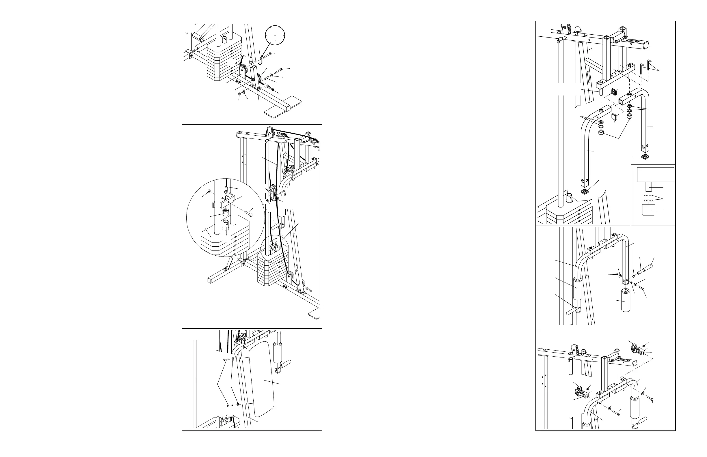
23. Hold the indicated end of the Short Cable (23)
under the 3 1/2” Pulley (15) on the Front Upright
(42). Attach the 5/16” x 3 1/2” Bolt (87), two 5/16”
Flat Washers (8), the 1” Metal Spacer (22), and a
5/16” Nylon Locknut (3) to the Front Upright as
shown. Be sure that the Short Cable is
between the Pulley and the Metal Spacer.
Tighten the 3/8” Nylon Locknut (21) and 3/8” x
3 1/2” Bolt (not shown).
Wrap the Short Cable (23) up around the 3 1/2”
Pulley (15) on the Pulley Plate (20). Tighten the
3/8” Nylon Locknut (21) and 3/8” x 1 3/4” Bolt
(48). Make sure that the Cable Trap (59) is in
the 6 o’clock position.
24. Remove the 3/8” Nylon Locknut (21), 3/8” x 1 3/4”
Bolt (48), and 4 1/2” Pulley (77) from the lower
end of the “I” Plates (78). Route the Short Cable
(23) over the Pulley and reattach the Pulley to the
“I” Plates with the Bolt and Nylon Locknut.
Refer to the inset drawing. Slide the Plastic
Flanged Bushing (103) onto the Weight Tube
(80). Press the Plastic Flanged Bushing into the
top Weight (25). Slide the Weight Guide Bracket
(81) onto the top of the Weight Tube. Tap the
Weight Guide Bracket with a mallet to ensure
that the Plastic Flanged Bushing is firmly in
the top Weight.
Insert the end of the Short Cable (23) into the
upper end of the Weight Tube (80). Insert a 5/16”
x 1 1/2” Bolt (24) through the Weight Guide
Bracket (81), Weight Tube, and Short Cable.
Tighten a 5/16” Nylon Locknut (3) onto the Bolt.
IMPORTANT: The Short and Long Cables (23,
66) must be properly routed on the Pulleys,
and the Cables must be properly tightened. To
tighten the Cables, refer to TIGHTENING THE
CABLES on page 18 of this manual.
25. Attach the Backrest (41) to the Front Upright (42)
with two 1/4” x 2 1/2” Screws (43) and 1/4” Flat
Washers (10).
25
43
42
41
10
23
24
87
48
59
8
22
23
23
66
81
3
25
103
80
23
78
77
48
21
24
8
3
15
42
15
21
20
9
12. Press two 1 3/4” Inner Caps (44) into each of the
Arms (46).
Apply lubricant to the lower axles on the Arm
Frame (52). Slide an Arm (46) onto one of the
axles. Hold two 1” Retainers (54) and a 1” Round
Cover Cap (55) against the lower end of the axle.
The teeth on the Retainers must bend toward
the Round Cover Cap (see inset drawing). Tap
the Retainers and Round Cover Cap onto the axle.
Attach the other Arm (46) to the Arm Frame (52) in
the same manner.
Insert the two 4 1/2” “L” Pins (60) down through the
indicated holes in the Arm Frame (52) and the
Arms (46).
13. Wet both Arms (46) with soapy water. Slide a 7 3/4”
Pad (45) onto each Arm.
Press a 1” Round Inner Cap (49) into the indicated
end of a 7” Handle (47). Wet the other end of the
Handle with soapy water and slide a Handgrip (12)
onto it. Insert the Handle into one of the Arms (46).
Attach the Handle with a 5/16” x 2 1/4” Bolt (33),
two 5/16” Flat Washers (8), a 1/2” x 3/8” Spacer
(51) and a 5/16” Nylon Locknut (3).
Attach a 7” Handle (47) to the other Arm (46) in the
same manner.
14. Attach a Large “U” Bracket (56) to one of the Arms
(46) with a 3/8” x 2 3/4” Bolt (70), 3/8” Flat Washer
(9), and 3/8” Nylon Locknut (21). Be sure that the
Cable Trap (59) is on the side shown.
Attach a Large “U” Bracket (56) to the other Arm
(46) in the same manner.
14
21
56
70
70
21
59
59
56
9
9
46
46
12
55
44
47
12
45
8
49
8
46
46
3
46
46
44
52—Lubricate
54
60
44
44
42
54
13
55
52
54
47
33
45
51