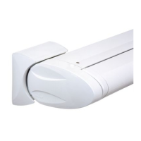
Angle Adjustment Mechanism for Topas with and without hood
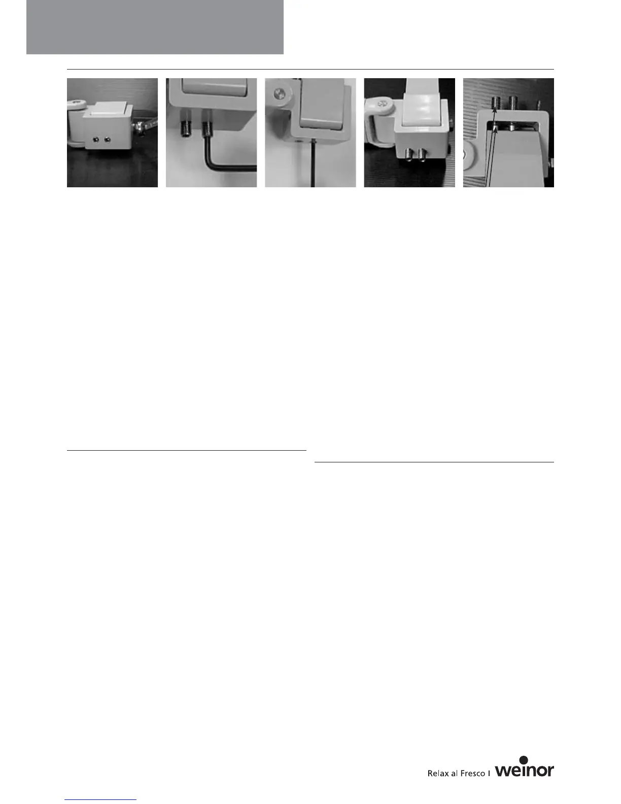
• Loosen the clamping nut (M10) on the tilting arm member (Pict 5).
• Adjusting the Pitch:
Turn both setscrews M10.
If turned inwards, the pitch becomes shallower (Pict 6)
If turned outwards, the pitch becomes sharper
Tighten the locking screw to a torque of 70 Nm to ensure the
mechanism has the greatest resistance to the wind force.
Check that the two adjusting screws are resting against the
thrust support (Pict 9).
The adjusting screws must, at the very most, be screwed in only
as far as to lie flush with the tilting arm member (Pict 7).
Only unscrew the unit when it is certain that all of the threads on
the tilting arm member can support the adjusting screws (Pict 8).
View of the bracket from below (Pict 9):
The adjusting screws have been loosened as far as permissible.
The last of the thread can still be seen here.
㛯㛯㛯
Cassette Pitch Adjustment for Cassita
To adjust the pitch it is not necessary to remove the caps. Apply
the Allen key (SW 8) as shown in Pict 10 and turn to the required
pitch. This should be performed gradually and alternately on both
sides.
Réglage de l’inclinaison de Topas avec et sans toit
• Desserrer la vis de serrage (M10) au niveau de la pièce
d’inclinaison (Pict 5).
• Réglage de l’inclinaison :
Tourner les deux tiges filetées M10.
Visser : l’angle d’inclinaison diminue (Pict 6).
Dévisser : l’angle d’inclinaison augmente.
La vis de serrage doit être serrée avec un couple de 70 Nm afin
d’atteindre la plus haute résistance par rapport au vent. Vérifier
que les deux vis de réglage reposent au niveau du support de
poussée (Pict 9).
Les vis de réglage peuvent être vissées de sorte qu’elles affleurent
tout au plus la pièce d’inclinaison (Pict 7).
Les vis peuvent être dévissées de sorte que tous les filets de la
pièce d’inclinaison portent les vis de réglage (Pict 8).
Vue du support de poussée par le bas (Pict 9) :
Les vis de réglage sont dévissées au maximum.
Le dernier pas de vis est encore visible.
㛯㛯㛯
Réglage de l’inclinaison de la cassette du store Cassita
Il n’est pas nécessaire de retirer les caches pour le réglage de
l’inclinaison de la cassette. Insérer la clé Allen (clé de 8) comme
représenté (Pict 10) et la tourner jusqu’à obtention de l’inclinaison
souhaitée. Cela doit être effectué étape par étape en alternant
des deux côtés.
Important Information
Informations importantes
㛯㛯㛯
8
Folding arm awnings
Pict 5 Pict 6 Pict 7 Pict 8 Pict 9
 Loading...