11
ASSEMBLY & ADJUSTMENTS
WARNING: Do not plug in or turn on the tool until it is fully assembled according to the instruc-
tions. Failure to follow the safety instructions may result in serious personal injury.
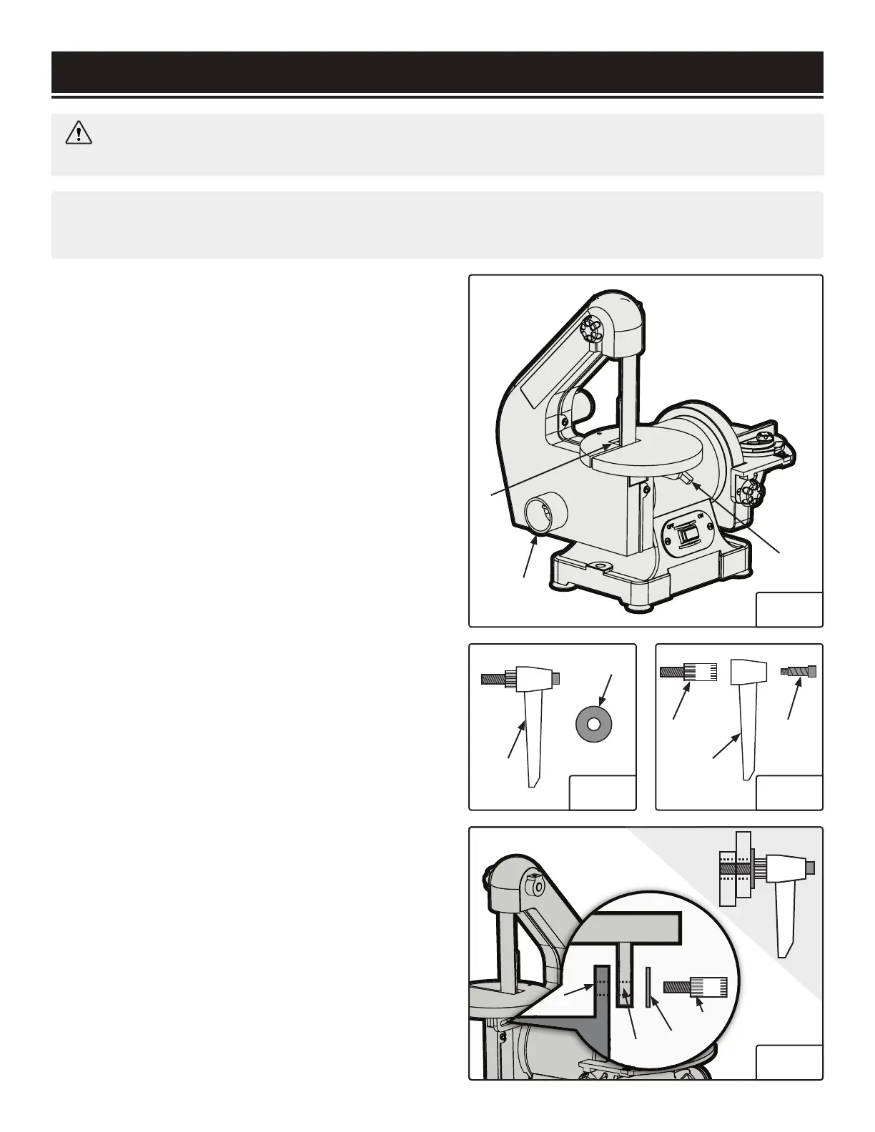
INSTALL SANDING BELT TABLE
1. Pass the sanding belt through the slot on the belt table
(Fig. 2 - 1) and position the table on the machine.
2. Secure the belt table into position using the locking lever
(Fig. 2 - 2). NOTE: You will have to follow the instructions
below to install the locking lever before you can use it to
secure the belt table.
Install the locking lever:
1. Gather the locking lever assembly (Fig. 3 - 1) and washer
(Fig. 3 - 2).
2. Disassemble the locking lever into the three parts shown
in Fig. 4. Using the 3mm hex wrench, remove the socket
head cap screw with spring (Fig. 4 - 3) from the lever handle
(Fig. 4 - 2). This will release the lever base (Fig. 4 - 1).
3. Align the slot in the belt table (Fig. 5 - 2) with the tapped
hole (Fig. 5 - 1) in the housing located underneath the table.
4. By hand, screw the lever base (Fig. 5 - 4) and washer (Fig.
5 - 3) into the tapped hole (Fig. 5 - 1), turning clockwise.
5. Place the lever handle (Fig. 4 - 2) onto the tightened lever
base (Fig. 5 - 4). Then, re-install the socket head cap screw
and spring (Fig. 4 - 3) through the lever handle. Tighten us-
ing the 3mm hex wrench. See the final assembly in the top
right-hand corner of Fig. 5.
NOTE: The lever is spring-loaded, and can be loosened and
re-positioned to allow you to make adjustments to the table
bevel, as desired. Always make sure the table is securely
locked down before beginning to sand.
NOTE: Before making any adjustments check that the power switch is in the OFF position and that the
plug is disconnected from the power source.
Fig. 2
1
2
1
1
2
2
3
4
1
2
3
3
Fig. 3 Fig. 4
Fig. 5

 Loading...