12
ASSEMBLY
Unpacking
• Remove all packaging materials.
• Remove remaining packing and package inserts (if included).
• Check that the package contents are complete.
• Check the appliance, the power cord, the power plug and all accessories for
transportation damage.
• Keep the packing materials as long as possible until the end of the warranty
period.
WARNING
Packaging materials are not toys! Children must not play with plastic bags!
Danger of suffocation!
INSTALLATION OF RUBBER
FEET (Fig. 1)
• Insert the rubber feet into the
4 holes in the base (fig. 1).
INSTALLATION OF THE
DIAMOND DISC AND METAL
BRACKET (Fig. 2-12)
• Unplug the tile saw from the mains
supply.
• Remove the cover (45º vertical
fence) of the water tank (fig. 2).
• Remove the fixing screw & washer
of the blade guard (fig. 3).
• Swing the blade guard then lift it
out of the notch (fig. 4-5).
• Remove the nut and outer flange
from the spindle (fig. 6).
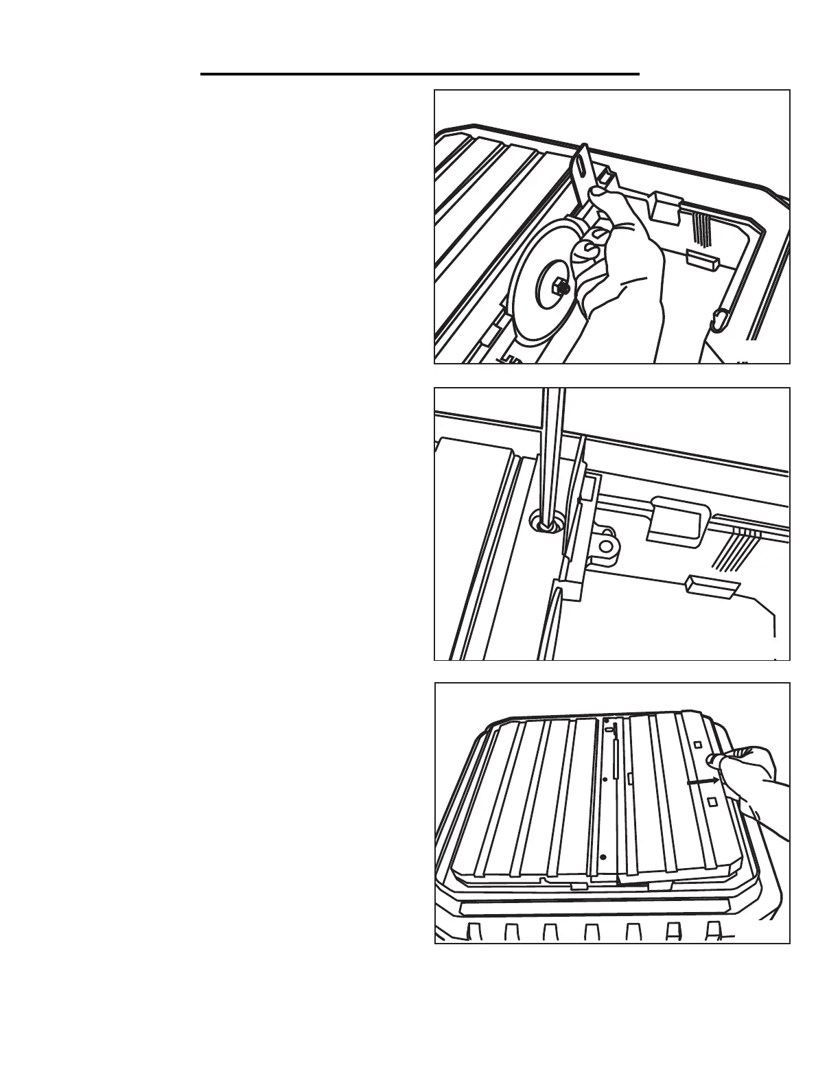
• Fit the diamond disc (fig. 7). Please
pay attention to the rotation
direction on the diamond disc. The
direction arrows on the disc must
be in the same direction as that
marked on housing.
• Ensure the diamond disc is fully
located and centred.
fig.7
fig.1 fig.2
fig.3 fig.4
fig.5 fig.6
fig.8
ASSEMBLY & ADJUSTMENTS
13
ASSEMBLY
• Replace the outer flange and nut and
tighten securely with the two spanners
provided (fig. 8). Check that both
blade flanges are in contact with the
blade.
• Unscrew the screw & washer from
the metal bracket (fig. 9).
• Put the metal bracket under the
plastic housing then slide it into the
slot (fig. 10-11).
• The metal bracket can be fixed into
position using the screw supplied
(fig. 12). Ensure the metal bracket is
in line with the diamond disc.
• Insert the blade guard into the notch
then tighten the screw (fig. 3).
• Put the cover (45º vertical fence)
back into position.
INSTALLATION OF THE
PROTECTIVE GUARD (Fig. 13-14)
• Unplug the tile saw from the mains
supply.
• Place the guard onto the metal
bracket (fig. 13) and fix in place using
the screw and washer. Push the
red cover cap over the nut (fig. 14).
• Cover the diamond disc with
the guard.
• Ensure that protective guard can
move freely and that it cannot touch
the disc.
• Do not over tighten the protective
guard when fixing it. The guard
should be free to rise and fall as the workpiece is pushed towards the disc.
INSTALLATION OF THE PARALLEL GUIDE (Fig. 15-16)
• Unplug the tile saw from the mains supply.
• Put the parallel guide onto the working table and fix it using the plastic securing
knobs (fig. 15).
• Mitre cutting can be performed by using the mitre cutting guide. The angle can
be adjusted from 0° to 45° by unscrewing the red palstic screw.
• To perform 45° bevel cut, raise one side of the table, lever out the support and
locate the labs into the corresponding holes in the deck (fig. 16).
Ensure that the deck is correctly secured before working.
fig.10
fig.12
fig.14
fig.16
fig.9
fig.11
fig.13
fig.15
(Continued)
7. Place the metal bracket under the plastic housing
then slide it into the slot (Fig. J). Fix the metal bracket
into position using the screw and washer previously re-
moved. Ensure that the metal bracket is in line with the
diamond disc.
13
ASSEMBLY
• Replace the outer flange and nut and
tighten securely with the two spanners
provided (fig. 8). Check that both
blade flanges are in contact with the
blade.
• Unscrew the screw & washer from
the metal bracket (fig. 9).
• Put the metal bracket under the
plastic housing then slide it into the
slot (fig. 10-11).
• The metal bracket can be fixed into
position using the screw supplied
(fig. 12). Ensure the metal bracket is
in line with the diamond disc.
• Insert the blade guard into the notch
then tighten the screw (fig. 3).
• Put the cover (45º vertical fence)
back into position.
INSTALLATION OF THE
PROTECTIVE GUARD (Fig. 13-14)
• Unplug the tile saw from the mains
supply.
• Place the guard onto the metal
bracket (fig. 13) and fix in place using
the screw and washer. Push the
red cover cap over the nut (fig. 14).
• Cover the diamond disc with
the guard.
• Ensure that protective guard can
move freely and that it cannot touch
the disc.
• Do not over tighten the protective
guard when fixing it. The guard
should be free to rise and fall as the workpiece is pushed towards the disc.
INSTALLATION OF THE PARALLEL GUIDE (Fig. 15-16)
• Unplug the tile saw from the mains supply.
• Put the parallel guide onto the working table and fix it using the plastic securing
knobs (fig. 15).
• Mitre cutting can be performed by using the mitre cutting guide. The angle can
be adjusted from 0° to 45° by unscrewing the red palstic screw.
• To perform 45° bevel cut, raise one side of the table, lever out the support and
locate the labs into the corresponding holes in the deck (fig. 16).
Ensure that the deck is correctly secured before working.
fig.10
fig.12
fig.14
fig.16
fig.9
fig.11
fig.13
fig.15
8. Insert the lower blade guard back into the notch and
then tighten the screw (Fig. K).
9. Place the 45° bevel table back into position (Fig. L).
Fig. J
Fig. K
Fig. L
11
 Loading...