ASSEMBLY & ADJUSTMENTS
INSTALLING THE SPINDLE
1. Insert the spindle shaft (Fig. 1 - 1) into the spindle hole
through the table opening. Spindle thead is M10-1.5.
2. Using one spindle wrench to hold the spindle seat in
place, thread the bottom of the spindle shaft onto the
spindle seat clockwise until it is hand-tight.
3. Place the second spindle wrench onto the retaining nut
of the spindle and securely tighten the spindle.
Fig. 1
ACCESSORY SELECTION
Refer to the packing list diagram on page 10 to ensure that you are using the proper sizes of throat plates,
drums and washers for each respective sanding sleeve. To ensure the workpiece can be properly supported and
to minimize clearance, use the throat plate that matches the drum
and sleeve that you’ll be working with. The
size of the throat plate is marked on the plate's surface. For horizontal sanding, use throat plates with circle
openings; for bevel sanding, use plates with an oblong openings.
NOTE: The smallest size sanding sleeve does not include a drum. It goes directly onto the bare spindle.
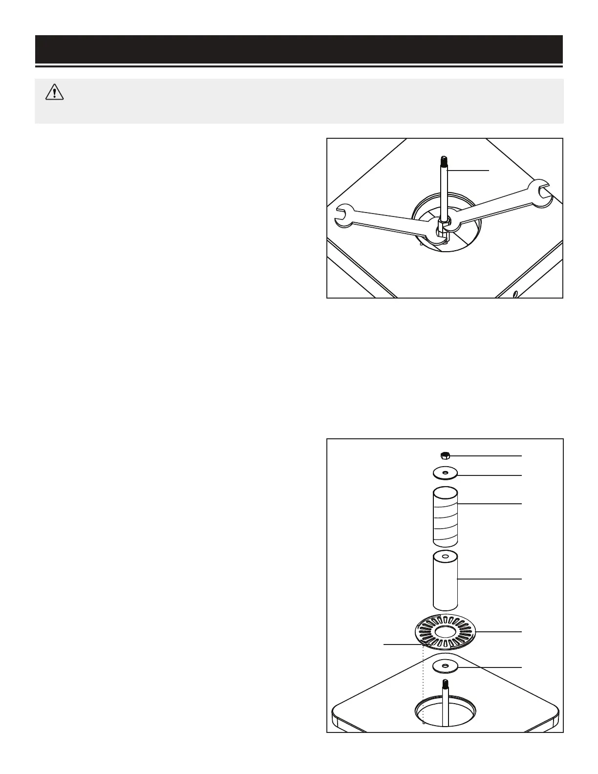
INSTALLING THE ACCESSORIES
1. Disconnect the machine from the power source.
2. Slide the lower spindle washer (Fig. 2 - 1) over the
spindle shaft.
3. Install the preferred rubber drum (Fig. 2 - 2) onto the
spindle shaft, followed by the corresponding sanding
sleeve (Fig. 2 - 3) and throat plate (Fig. 2 - 4). Make
sure the printed side of the throat plate is facing up.
NOTE: The 1/2" sleeve should be installed directly onto
the spindle.
4. Secure the sanding accessories in place with the cor-
responding washer (Fig. 2 - 5). Tighten the spindle nut
on top (Fig. 2 - 6) with the spindle nut wrench until the
sanding drum creates equal pressure to all sides of the
sanding sleeve. The sleeve should not be able to freely
rotate without also rotating the sanding drum.
Fig. 2
1
Align with
the notch
3
5
6
1
2
4
11
WARNING: To prevent accidental starting, make sure the machine is switched OFF and the power
plug is disconnected before assembly, setting up or making adjustments.

 Loading...