A A
B B
C C
D D
E E
F F
G G
H H
J J
K K
L L
M M
N N
P P
R R
T T
24
24
23
23
22
22
21
21
20
20
19
19
18
18
17
17
16
16
15
15
14
14
13
13
12
12
11
11
10
10
9
9
8
8
7
7
6
6
5
5
4
4
3
3
2
2
1
1
DRAWN
CHK'D
APPV'D
MFG
Q.A
UNLESS OTHERWISE SPECIFIED:
DIMENSIONS ARE IN MILLIMETERS
SURFACE FINISH:
TOLERANCES:
LINEAR:
ANGULAR:
FINISH:
DEBURR AND
BREAK SHARP
EDGES
NAME
SIGNATURE
DATE
MATERIAL:
DO NOT SCALE DRAWING
REVISION
TITLE:
DWG NO.
SCALE:1:5
SHEET 1 OF 1
A0
WEIGHT:
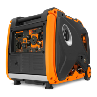
GLT WEN4750
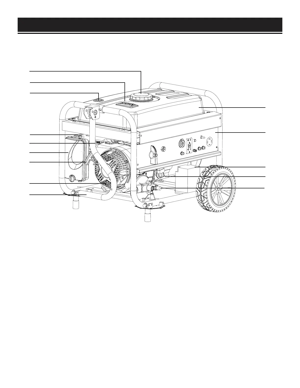
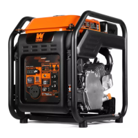
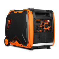
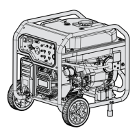
KNOW YOUR GENERATOR
8
1. Gasoline Fuel Cap
Access to the fuel tank for adding gasoline
2. Fuel Gauge
Indicates amount of fuel inside the fuel tank
E indicates Empty, F indicates Full
3. Pressure Relief Valve
4. Choke Lever
Adjusts the amount of air let into the engine
during startup
5. Fuel Valve
Allows fuel to enter engine from the fuel tank
6. Air Filter
A case with a sponge-like element that filters the air
entering the engine
7. Recoil Starter
Pull cord for manually starting the engine
1
2
3
4
5
6
7
8
9
8. 224cc OHV Engine
9. Transportation Handle
For easy transport of the generator
(installed by user)
10. Fuel Tank
12. Control Panel
Refer to the next page for descriptions
11. Battery
Connect the battery before starting the generator
12. Oil Fill and Dipstick
For filling and checking oil
13. LPG Hose Connector
Connects to LPG hose and LPG cylinder
12
11
10
13
Use the illustration below to become familiar with all the components and controls of this generator. If any part is
damaged or missing, please contact our customer service at (800) 232-1195, M-F 8-5 CST or email us at techsup-
port@wenproducts.com.
14