ENGINE
ADJUSTMENTS
NOTE:
WESTERBEKE
recommends
that
the
following
engine
adjustments
.be
petformed
by
a
competent
engine
mechanic.
The
information
below
is
provided
to
assist
the
mechanic.
VALVE
CLEARANCE
ADJUSTMENT
(CDNT.)
5.
When setting
IDe
for
the
No.2 cylinder proceed
as
follows:
a. For the two engine
(2
cylinder) from
IDC
for
the
No.1
cylinder, rotate
the
crankshaft
180
0
clockwise
(as
viewed from
the
front
of the engine)
and
adjust
the
valve clearances
for
both
the
intake
and
exhaust valves
for
the
No.2
cylinder.
Rotate the crankshaft another 240 clockwise
to,
position theNo,2 cylinder at
IDC.
Adjust
the
valve
clearances for
both
the
intake and exhaust valves for
the No.2 cylinder.
Injection
Pump
Timing
Adjustment
(Spill
Timing)
The shut·off lever (throttle)
must
be in the
run
position
and
the throttle fully open
while
making
these adjustments or
no
fuel will
flow
to the injection
pump.
.
Remove
the
cylinder glow
plugs
to
allow the engines
crankshaft
to
be easily rotated.
1. Remove the high pressure
fuel
line from between the
No.1
injector and
the
No.1
fuel
delivery valve
holder.
2. Remove the
No.1
fuel
delivery valve holder over the
"0"
ring
and remove
the
delivery valve spring beneath
the
holder.
3. Reinstall only the delivery valve holder
and
re·attach
the
high pressure
fuel
line to
the
delivery
holder.
Attach it
so
that
the
end that
would
connect to the fuel injector is .
pointing away
from
the
engine.
Fuel will
flow
from
this
line during the timing
check.
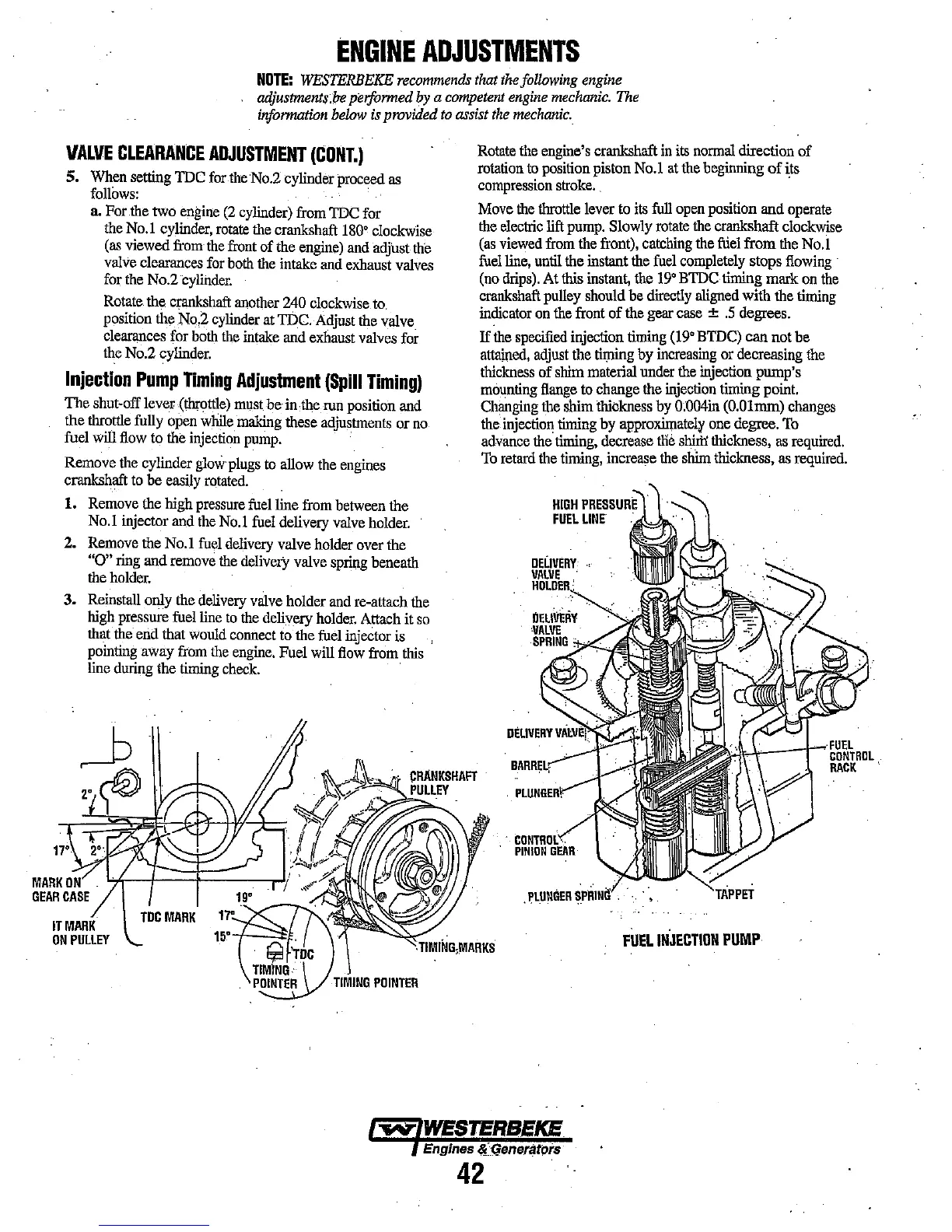
IT
MARK
ON
PULLEY
Rotate
the
engine's crankshaft
in
its
normal
direction of
rotation
to
position piston
No.1
at
the
beginning
of
its
compression stroke.
, .
Move
the
throttle lever to
its
full
open position and operate
the
electric lift
pump.
Slowly rotate
the
crankshaft clockwise
(as
viewed
from
the
front), catching
the
friel
from
the
No.1
fuel
line, until the instant
the
fuel
completely stops
flowing
,
(no
drips).
At this instant, the
19
0
BIDCtiming mark
on
the
crankshaft pulley should be directly aligned with the timing
indicator
on
the
front of the gear case ±
.5
degrees.
If
the
specified
injection timing
(19
0
BIDC) can not be
attained,
adjust
the timing by increasing or decreasing
the
thickness
of shim material under
the
injection pump's
mounting
flange
to change the injection timing point.
Changing the shim thickness by
0;004in
(O.01mm)
changes
the
injection timing by approxilllately one degree.
To
advance the timing, decrease
tile
shitt! thickness,
as
required.
To
retard
the
timing,
increase
the
shim thickness,
as
required.
HIGH
PRESSURE
FUEL
LINE
'!\,-+---t'"'"'
FUEL
...
CONTROL
RACK
FUEL
INJECTION
PUMP
"'iIV'
WESTERBEKE
Engines
1I<:4eneratprs
42