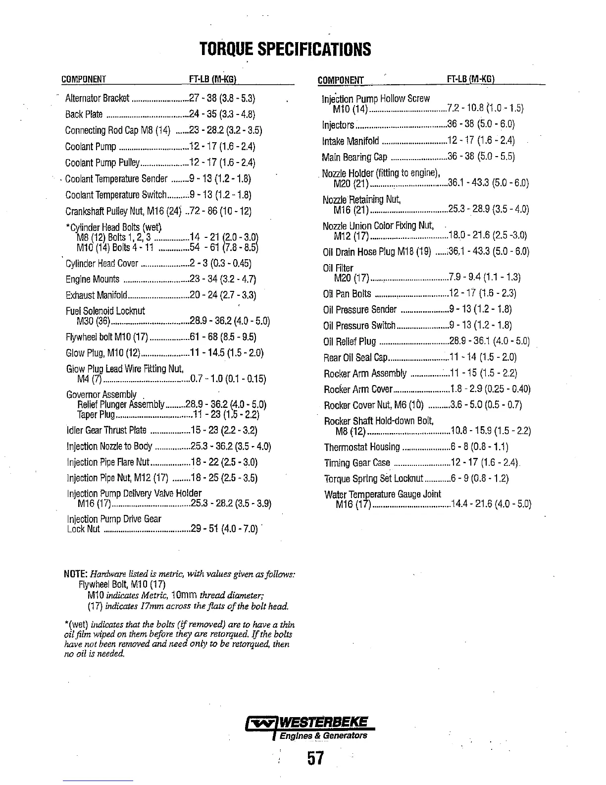
TORQUE
SPECIFICATIONS
COMPONENT
FHB
(M-KG)
Alternator
Bracket
..........................
27
-
38
(3.8
-
5.3)
Back
Plate
......................................
24
-
35
(3.3
-
4.8)
Connecting
Rod
Cap
M8
(14)
......
23
-
28.2
(3.2
-
3.5)
Coolant
Pump
................................
12
-
17
(1.6
-
2.4)
Coolant
Pump
Pulley
......................
12
-
17
(1.6
-
2.4)
.
CoolantTemperature
Sender
........
9 -
13
(1.2
-
1.8)
CoolantTemperature
Switch
..........
9 -
13
(1.2
-
1.8)
Crankshaft
Pulley
Nut,
M16
(24)
..72
-
86
(10
-
12)
'Cylinder
Head
Bolts
(wet)
M8
(12)
Bolts
1,
2,
3
................
14
-
21
(2.0
-
3.0l
M10
(14)
Bolts
4 -
11
..............
54
-
61
(7.8
-
8.5
Cylinder
Head
Cover
......................
2 - 3
(0.3
-
0.45)
Engine
Mounts
..............................
23
-
34
(3.2
-
4.7)
Exhaust
Manifold
..........................
..20
-
24
(2.7
-
3.3)
Fuel
Solenoid
Locknut
M30
(36)
....................................
28.9
..
36.2
(4.0
-
5.0)
Flywheel
bolt
M1
0
(17)
..................
61
-
68
(8.5
-
9.5)
Glow
Plug,
M10
(12)
......................
11
-
14.5
(1.5
-
2.0)
Glow
Plug
Lead
Wire
Fitting
Nut,
M4
(7)
........................................
0.7
-
1.0
(0.1
-
0.15)
Governor
Assembly
.
Relief
Plunger
Assembly
.........
28.9
-
36.2
(4.0
-
5.0)
Taper
Plug
...................................
11
-
23
(1.5
-
2.2)
Idler
Gear
Thrust
Plate
..................
15
-
23
(2.2
-
3.2)
Injection
Nozzle
to
Body
................
25.3
-
36.2
(3.5
-
4.0)
Injection
Pipe
Flare
NuL
...............
18
-
22
(2.5
-
3.0)
Injection
Pipe
Nut,
M12
(17)
........
18
-
25
(2.5
-
3.5)
Injection
Pump
Delivery
Valve
Holder
M16
(17)
....................................
25.3
-
28.2
(3.5
-
3.9)
Injection
Pump
Drive
Gear
Lock
Nut
........................................
29
-
51
(4.0
-
7.0)
.
NOTE:
Hardware listed
is
metric, with values given
as
follows:
Flywheel
Bolt,
M1
0
(17)
M10
indicates Metric,
10mm
thread diameter;
(17)
indicates 17mm across the flats
of
the bolt head.
'(wet)
indicates that the bolts
(if
removed) are to have a thin
ai/film wiped on them before
they are retorqued.Ifthe bolts
have not
been
removed
and need only
to
be
retorqued,
then
no
oil
is
needed,
COMPONENT
FHB
(M-KG)
Injection
Pump
Hollow
Screw
.
M10
(14)
....................................
7.2
-
10.8
(1.0
-
1.5)
Injectors
..........................................
36
-
38
(5.0
-
6.0)
Intake
Manifold
..............................
12
-
17
(1.6
-
2.4)
Main
Bearing
Cap
..........................
36
-
38
(5.0
-
5.5)
.
Nozzle
Holder
(fitting
to
engine),
M20
(21)
...........
,
........................
36.1
-43.3
(5.0
-6.0)
Nozzle
Retaining
Nut,
M16
(21)
....................................
25.3
-
28.9
(3.5
-
4.0)
Nozzle
Union
Color
Fixing
Nut,
M12
(17)
....................................
18.0
-
21.6
(2.5
-3.0)
Oil
Drain
Hose
Plug
M18
(19)
.....
:36.1
-
43.3
(5.0
-
6.0)
Oil
Filter
M20
(17)
......
,
.............................
7.9
-
9,4
(1.1
-
1.3)
Oil
Pan
Bolts
..........
,
.......................
12
-
17
(1.6
-
2.3)
Oil
Pressure
Sender
......................
9 -
13
(1.2
-
1.8)
Oil
Pressure
Switch
........................
9 -
13
(1.2
-
1.8)
Oil
Relief
Plug
................................
28.9
-
36.1
(4.0
-
5.0)
Rear
Oil
Seal
Cap
............................
11
-
14
(1.5
-
2.0)
Rocker
Arm
Assembly
..................
11
-
15
(1.5
-
2.2)
Rocker
Arm
Cover
..........................
1.8
-
2.9
(0.25
-
0.40)
Rocker
Cover
Nut,
M6
(10)
..........
3.6
-
5.0
(0.5
-
0.7)
Rocker
Shaft
Hold-down
Bolt,
M8
(12)
......................................
1
0.8
-
15.9
(1.5
-
2.2)
Thermostat
Housing
......................
6 - 8
(0.8
-
1.1)
Timing
Gear
Case
..........................
12
-
17
(1.6
-
2.4).
Torque
Spring
Set
Locknut
............
6 - 9
(0.8
-
1.2)
Water
Temperature
Gauge
Joint
M16
(17)
....................................
14.4
-
21.6
(4.0
-
5.0)
-.N"
WES~RBEKE
Engines
~Generators
57