HURTH
ifBWJZF
TRANSMISSIONS
DESCRIPTION
The
infonnation below
is
specific
to
the
Haw
Transmissions,
the
TRANSMISSION
TROUBLESHOOTING
SECTION
applies
to
all
models.
INCLINATION
A
CAUTION:
The
position
of
the
mechanism
behind
the
actuating
lever
Is
factory-adjust(ld
to
ensure
equal
shift
lever
travel
from
neutral
positio';
A
and·B.
If
this
mechanism
Is
in
any
way
tampered
with,
the
transmisSion
warranty
wili
be
void.
SHAFT
COUPLINGS
WESTERBEKE
recommends a flexible connection
between
the
transmission and
the
propeller shaft if the engine
is
flexi-
bly
mounted,
in
order
to
compensate for angular
deflections.
The
installation of a
special
propeller thrust bearing
is
not
required,
since the propeller thrust will
be
absorbed
by
the
transmission bearing, provided the value specified under .
SPECIFICATIONS
is
not
exceeded.
However,
the
output
shaft should
be
protected from additional loads.
S,pecial
care
should be taken to prevent torsionpi vibratipn. When using a
universal joint shaft,
make
certain' to observe the
manufacturers
instructions-.
Even
with
the
engine
solidly
mounted,
the
use
of
flexible
coupling or
uDRlVESAVER"
will
reduce stress in the
gear:.
box
bearings
caused
by
hull distortions, esp,cially
in
wooden
boats
or
where
the
distance
between transmission output
flange
and
stem gland
is
less
than about 800mm.
NOTE:
When
installing
the
transmission,
make
certain that
shifting
is
not
impeded
by
restricted
movability
of
the·
cable
or
rod
linkage,
by
unsuitably
positioned
guide
sheaves,
too
small
a
bending
radius
or
other
restrictions.
In
order
to
mount a
support
for
shift
control
cable
connections,
use
the
two
threaded
holes
located
above
the
cable
bracket
mounted
on
the
gear
housing.
Refer
to
the
WESTERBEKE
parts
list.
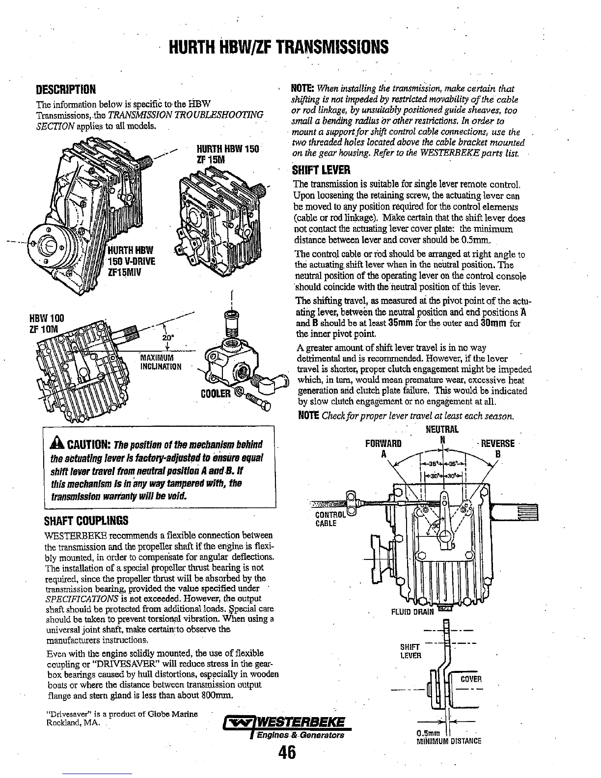
SHIFT
LEVER
The transmission
is
suitable
for
single lever remote control.
Upon loosening the retaining
screw,
the
actuating lever can
be moved
to
any
position required
for
the
control elemelllS
(cable or
rod
linkage).
Milke
certain
that
the shift lever
does
not contact
the
actuating lever cover
plate:
the
minimum
distimce
between
lever and cover
should
be
O.5mm.
The control
cable
or rod should be
arranged
at
right angle
to
the
actuating.
shift lever
when
in
the
neutral
position. The
neutral
position
of
the
operating lever
on
the
control console
·should coincide with
the neutral position of
this
lever.
The shifting travel,
as
measured
at
the
pivot point
o.f
the
actu-
ating
lever,
between
the
neutral
position
and
eM
positions A
and B should be at least
35mm
for the
outer
and
30mm
for
the inner pivot point. .
A greater amount
of
shift lever trayel
is
in
no
way
detrimental
and
is recommended.
However,
if
the lever
travel
is
shorter,
proper clutch engagement might be impeded
which,
in
turn,
would mean premature
wear,
ex.cessive
heat
generation
arid
clutch plate
failure.
This would
be
indicated
by
slow
clutch
engagement
or
no
engagement
at
all.
NOTE
Check
for proper
lever
travel
at
least
each
season.
CONTROL
CABLE
FORWARD
A
SHIFT
LEVER
NEUTRAL
.
REVERSE·
B
COVER
"Drivesaver" is a product
of
Globe Marine
Rockland,
MA.
~
WESTERBEKE
O.5mm
F
MINIMUM
DISTANCE
'Englnes&.Gellerators
46