FROM
FROM
WA7fR
TANK
DOMESTIC HOT WATER
TANK
CONNECTIONS
EXISTING
(CUT)
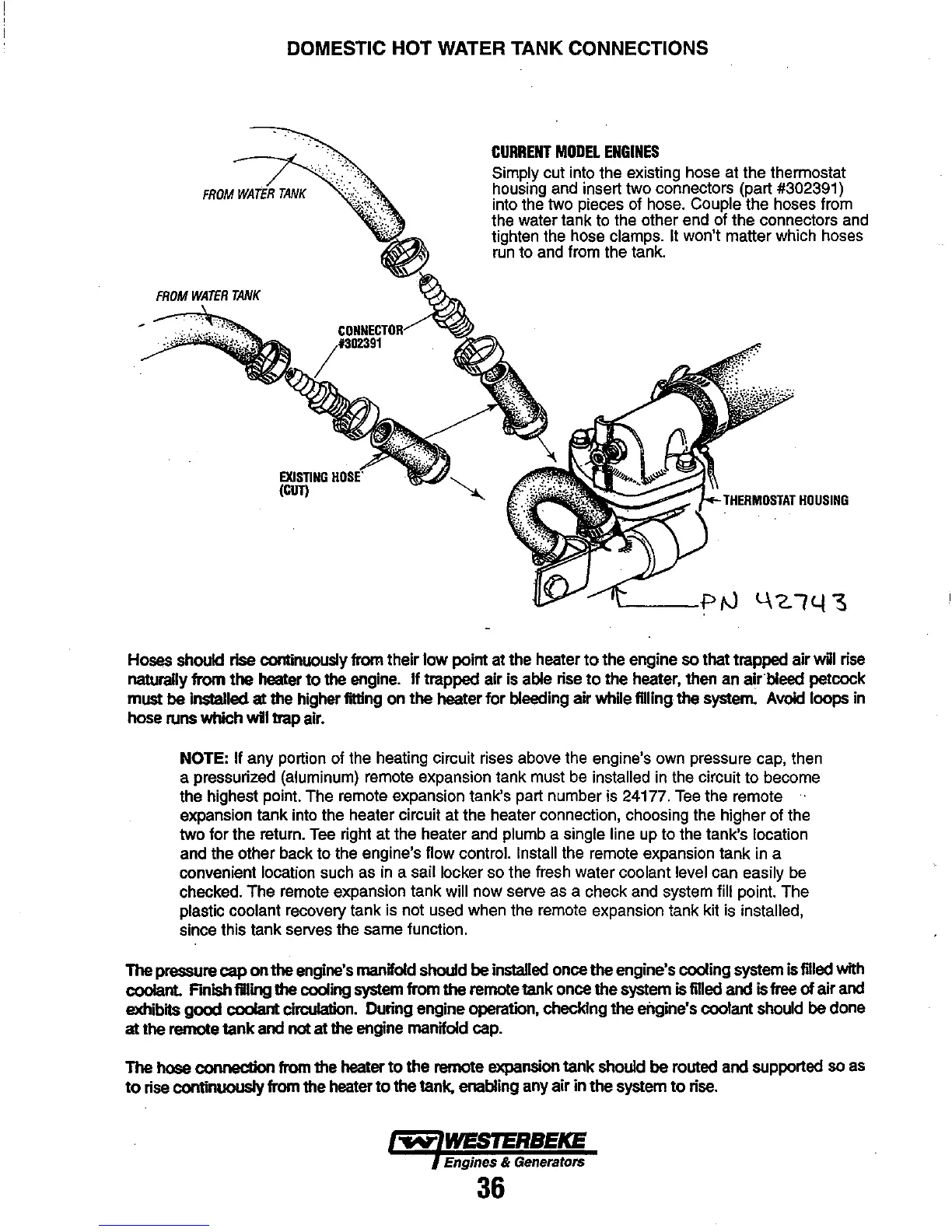
CURRENT
MODEL
ENGINES
Simply cut into the existing hose at the thermostat
housing and insert two connectors (part #302391)
into the two pieces of hose.
Couple the hoses from
the water tank to the other end of the connectors and
tighten the hose clamps.
It won't matter which hoses
run to and from the tank.
THERMOSTAT
HOUSING
Hoses should rise continuously from their
low
point at the heater
to
the engine so that trapped air will rise
naturally
from
the
heater
to
the engine.
If
trapped air is able rise
to
the
heater, then an
air
bleed petcock
must
be
inslalled at the higher fitting
on
the
heater
for
bleeding air
whUe
filling the system. Avoid loops in
hose runs which wli trap air.
NOTE: If any portion of the heating circuit rises above the engine's own pressure cap, then
a pressurized (aluminum) remote expansion tank must be
installed in the circuit to become
the highest point. The remote expansion tank's part number is 24177.
Tee
the remote
expansion tank into the heater circuit at the heater connection, choosing the higher of the
two for the return.
Tee
right at the heater and plumb a single line up to the tank's location
and the other back to the engine's flow control.
Install the remote expansion tank in a
convenient location such as in a sail locker so the fresh water coolant
level can easily be
checked. The remote expansion tank will now serve as a check and system
fill point. The
plastic coolant recovery tank is not used when the remote expansion tank kit is installed,
since this tank serves the same function.
The pressure cap
on
the
engine's manifold should
be
installed once the engine's cooling system is filled with
coolant. F'mish IDling the cooling system from
the
remote tank once
the
system is filled and is free
of
air
and
exhibits
good
coolant
circuIaIion. During engine operation, checking
the
engine's coolant should
be
done
at the remote
tank
and not at the engine manifold cap.
The hose connection from the heater
to
the
remote expansion
tank
should
be
routed and supported so as
to
rise continuously from the heater
to
the
tank, enabling any
air
in
the
system
to
rise.
~
WESTERBEKE
Engines & GeneratolS
36