BT
GENERATOR
TROUBLESHOOTING
RESIDUAL
VOLTAGE
CHECK
1. Residual Voltage 10-14 volts AC.
NOTE:
The amount
of
flO-load
voltage produced by the
generator can be an indicator
of
where in the generator
the problem/fault may
lie.
This voltage is the
AC
voltage produced by the generator
from magnetism in the exciter stator field. This voltage is
measured between the
AC
neutral and hot leg(s) with no-
load on the generator running at
60 hertz.
The
presence
of
residual voltage is an indication that the
following generator components are
OK:
1. Exciter Rotor (B-1 a, b, & C) & (B-2)
2. Rotating Field (B-3)
3. Main Stator (C-1
& C-2)
4. Compound Transformer (D-l
& D-2)
The
fault lies
in
one or more
of
the following compo-
nents
in
the exciter circuit:
.
A. Exciter Stator (A-1 & A-2)
B. Bridge Rectifier
(0)
C. Selector Switch (F)
D. Main Stator Auxiliary Windings (C-3)
E. Compound Transformer Auxiliary Winding (D-3)
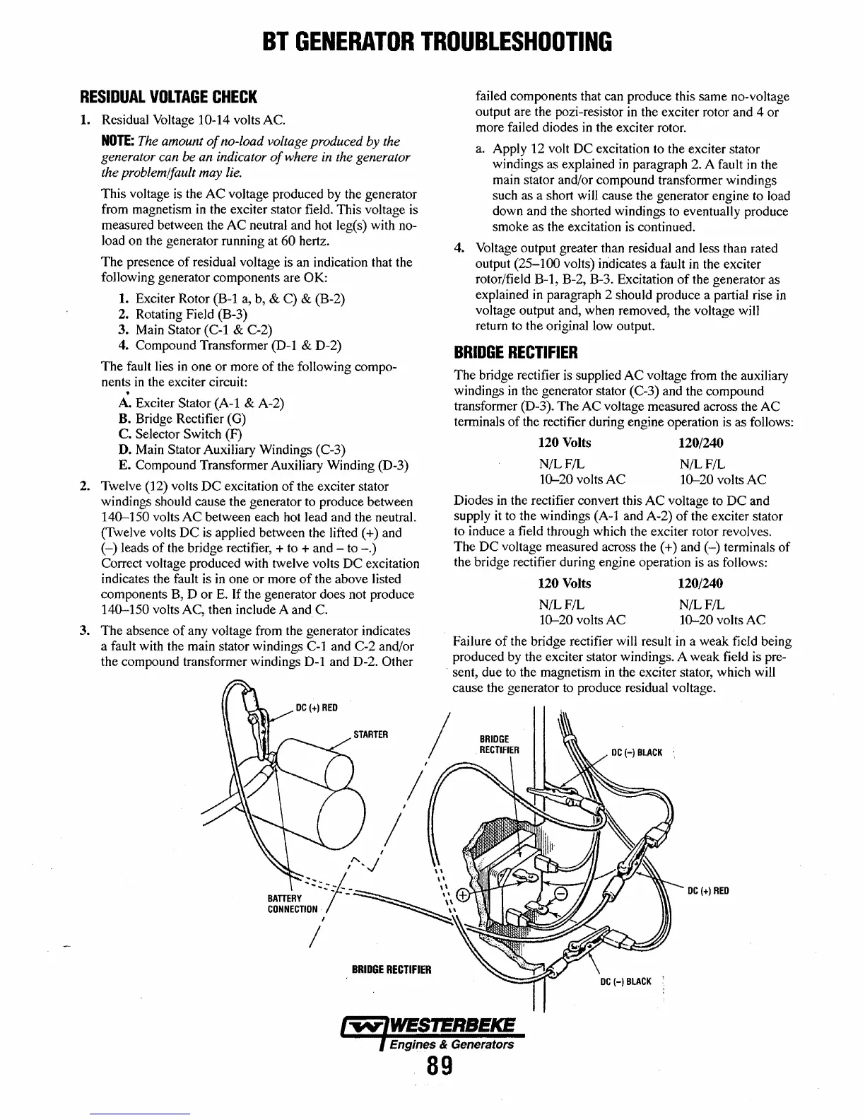
2. Twelve (12) volts
DC
excitation
of
the exciter stator
windings should cause the generator to produce between
140-150 volts
AC
between each hot lead and the neutral.
(Twelve volts
DC
is applied between the lifted
(+)
and
(-)
leads
of
the bridge rectifier, + to + and - to
-.)
Correct voltage produced with twelve volts
DC
excitation
indicates the fault is
in
one or more
of
the above listed
components B, D or
E.
If the generator does not produce
140-150 volts AC, then include A
and
C.
3. The absence
of
any voltage from the generator indicates
a fault with the main stator windings C-1 and C-2 and/or
the compound transformer windings
D-1
and D-2. Other
/
/
failed components that can produce this same no-voltage
output are the pozi-resistor
in
the exciter rotor and 4 or
more failed diodes
in
the exciter rotor.
a.
Apply 12 volt
DC
excitation to the exciter stator
windings as explained
in
paragraph 2. A fault
in
the
main stator and/or compound transformer windings
such as a short will cause the generator engine to load
down and the shorted windings to eventually produce
smoke as the excitation is continued.
4. Voltage output greater than residual and less than rated
output
(25-100
volts) indicates a fault
in
the exciter
rotor/field B-1, B-2, B-3. Excitation
of
the generator as
explained
in
paragraph 2 should produce a partial rise
in
voltage output and, when removed, the voltage
wi)]
return to the original low output.
BRIDGE
RECTIFIER
The bridge rectifier is supplied
AC
voltage from the auxiliary
windings
in
the generator stator (C-3) and the compound
transformer (D-3). The AC voltage measured across the
AC
terminals
of
the rectifier during engine operation
is
as follows:
120
Volts
120/240
NIL F/L N/L F/L
10-20
volts
AC
10-20 volts
AC
Diodes
in
the rectifier convert this
AC
voltage to
DC
and
supply
it
to the windings (A-l and A-2)
of
the exciter stator
to induce a field through which the exciter rotor revolves.
The
DC
voltage measured across the (+) and
(-)
terminals
of
the bridge rectifier during engine operation is as follows:
120
Volts
120/240
N/LF/L
N/LF/L
10-20
volts
AC
10-20
volts
AC
Failure
of
the bridge rectifier will result
in
a weak field being
produced by the exciter stator windings. A weak field is pre-
, sent, due to the magnetism in the exciter stator, which will
cause the generator to produce residual voltage.
/
DC
(+)
RED
BRIDGE
RECTIFIER
Engines & Generators
89