Do you have a question about the Westerbeke W-27A and is the answer not in the manual?
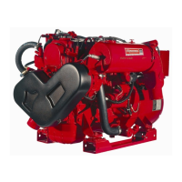
Lists marine diesel engine models covered in the manual.
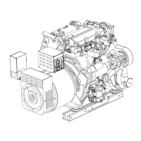
Lists marine diesel generator models covered in the manual.
Warning about diesel engine exhaust constituents and health risks.
Details symptoms and actions for carbon monoxide exposure.
Instructions to prevent electrical hazards during operation and maintenance.
Warnings and precautions related to hot engine components.
Safety guidelines to prevent fire hazards around fuel systems.
Precautions to prevent explosions from fuel vapors.
Procedures to prevent unintended engine starting.
Warnings regarding battery explosion and acid hazards.
Information on hazards of exhaust gases, especially carbon monoxide.
Warnings about hazards from rotating engine components.
Caution about potential hearing loss from high noise levels.
Importance of reading the operator's manual for safety and maintenance.
References to ABYC, NFPA, and USCG standards for engine installation.
Explains the purpose and scope of the service manual.
Defines the meaning of notes, cautions, and warnings used.
Guides on how to identify and order replacement parts.
Explains the model group designations used in the manual.
Fields for recording generator specifications.
Fields for recording engine specifications.
Detailed specifications for various Westerbeke engine and generator models.
Criteria and indicators for determining when an engine needs overhaul.
Procedure for measuring engine compression pressure.
Conditions requiring overhaul and reference to service standards.
Step-by-step instructions for disassembling the engine.
Step-by-step instructions for reassembling the engine.
Specifications for cylinder head distortion, valve seats, and valves.
Specifications for valve springs and rocker arms.
Specifications for cylinder block, bore, and taper.
Specifications for pistons, pins, and rings.
Specifications for connecting rods and bearings.
Specifications for crankshaft and main bearings.
Specifications for camshaft, pump camshaft, tappets, and push rods.
Specifications for engine oil, oil pump, and oil pressure switch.
Specifications for fuel injection pump and nozzles.
Torque specifications for various bolts and nuts.
Torque values for common screw sizes.
Specifies sealants for different parts and surfaces.
Troubleshooting for hard starting and defective injection systems.
Diagnosing and resolving common engine operating problems.
Troubleshooting low power output and insufficient fuel supply.
Diagnosing overheating, oil leaks, and excessive fuel consumption.
Troubleshooting engine knock, smoky exhaust, and nozzle issues.
Diagnosing smoky exhaust and abnormal engine noises.
Troubleshooting rough running and governor system faults.
Troubleshooting engine knocking and intermittent exhaust sounds.
Diagnosing overheating and issues with seized/damaged parts.
Illustrates and labels engine parts from the side.
Illustrates and labels engine parts from the front.
Describes the overhead valve design, material, and cooling features.
Details the precombustion chamber and valve guide construction.
Explains the construction of rocker arms, shaft, intake, and exhaust manifolds.
Step-by-step instructions for removing the cylinder head and its components.
Procedures for inspecting the cylinder head for damage and distortion.
Inspecting valve guides for clearance and valve seats for contact.
Inspecting valves, springs, and rocker arms for wear and damage.
Instructions for reassembling cylinder head components.
Procedures for installing the cylinder head assembly onto the engine.
Steps to adjust valve clearances for proper engine performance.
Describes the cylinder block's full jacket type, materials, and integrated liners.
Details main bearings, crankshaft, flywheel, and gear construction.
Explains piston, piston pin, and connecting rod design.
Describes camshaft, timing gears, and valve timing specifications.
Explains the function and construction of tappets, push rods, and injection pump camshaft.
Step-by-step instructions for disassembling the cylinder block.
Inspecting cylinder walls, bore wear, and piston ring gaps/clearance.
Measuring piston O.D. and checking piston pin for wear.
Inspecting connecting rods, crankshaft bend, and end play.
Checking main and connecting rod bearings for wear and proper installation.
Inspecting gearcase, camshaft, bearings, tappets, and push rods.
General instructions for reassembling cylinder block components.
Installing camshaft bushing and idler gear shaft.
Procedure for installing the dipstick guide.
Assembling pistons and connecting rods using the setting tool.
Proper installation of piston rings onto the piston.
Installing and aligning timing gears, oil pump gear, and injection pump camshaft.
Installing gear case and injection pump assemblies.
Explains the governor's role in maintaining engine speed.
Instructions for disassembling the governor assembly.
Explains manual stop lever and optional key switch shutoff operation.
Procedures for installing and verifying the key-stop solenoid.
Sequence and procedure for tightening cylinder head bolts.
Steps to adjust valve clearances for optimal engine performance.
Procedure for setting the fuel injection timing for correct combustion.
Additional method for checking injection timing and adjusting shims.
Procedure for setting no-load engine speeds for generators and propulsion models.
Description of the oil pump, filter, and oil galleries.
Steps for disassembling and inspecting the oil pump.
Reassembly of oil pump and testing oil pressure.
Explains the function of the oil pressure switch and sender.
Describes fuel lift pumps and primary fuel filters.
Details the four-cylinder fuel injection pump and its control rack.
Explains Angleich mechanism and fuel injection rate control.
Describes intercylinder control and nozzle operation.
Instructions for disassembling fuel filter and lift pump.
Steps for disassembling the fuel injection pump.
Inspecting injectors, filters, lift pumps, and injection pumps.
Procedures for reassembling fuel system components.
Instructions for installing injector assemblies.
Installing and adjusting the fuel injection pump.
Adjusting nozzle holder assembly start pressure and performing chattering test.
Performing after-drip and injection condition tests on injectors.
Final steps for installing the nozzle holder assembly.
Explains the function of the raw water circuit, pump, and heat exchanger.
Mentions transmission oil coolers used in some installations.
Steps for disassembling the PN 33636 raw water pump.
Inspecting and reassembling the PN 33636 raw water pump.
Steps for disassembling the PN 24143 raw water pump.
Inspecting and reassembling the PN 24143 raw water pump.
Describes water pump, thermostat, heat exchanger, and manifold.
Recommendations for flushing the system and using antifreeze.
Procedures for draining, disassembling, and inspecting the cooling system.
Testing the thermostat and adjusting drive belt tension.
Details the gauges, switches, and indicators on the Admiral panel.
Explains the high water temperature and low oil pressure alarms.
Details the gauges, buttons, and indicators on the Captain panel.
Troubleshooting common problems with tachometers and hourmeters.
Diagnosing issues with starter engagement, fuel solenoid, and ignition.
Troubleshooting water temperature and oil pressure gauges.
Describes the sequence of operations when using the key switch.
Describes starter sections and how to inspect pinion gap.
Procedure for performing a no-load test on the starter.
Tests for solenoid and steps for disassembling the starter motor.
Inspecting the solenoid and armature for faults.
Checking brushes and brush holders for wear and tension.
Inspecting field coils and reassembling the starter assembly.
Overview of the 12V DC control circuit and charging system.
Steps to diagnose issues with the alternator's output voltage.
Guidelines for maintaining engine starting and house batteries.
Explains glow plug function and how to test them.
Describes alternator function and initial troubleshooting steps.
Procedure for testing the alternator's charging voltage output.
Performing output tests and disassembling the alternator.
Inspecting diodes for short or open circuits.
Inspecting stator windings, field coils, brushes, and slip rings.
Explains regulator function and provides basic tests.
Procedures for reassembling the alternator, including alignment and belt tension.
Advises contacting manufacturers for specific transmission parts and service.
Electrical diagram for engine wiring configuration #24666.
Schematic for engine wiring configuration #24666.
Electrical diagram for engine wiring configuration #33685.
Schematic for engine wiring configuration #33685.
Electrical diagram for engine wiring configuration #36467.
Schematic for engine wiring configuration #36467.
Electrical diagram for engine wiring configuration #36844.
Schematic for engine wiring configuration #36844.
Electrical diagram for engine wiring configuration #39144.
Schematic for engine wiring configuration #39144.
Torque values for Grade 4 and Grade 7T bolts.
Torque values for Grade 6T bolts and Grade 5 cap screws.
Conversion factors for length measurements.
Conversion factors for length measurements in meters.
Conversion factors for weight measurements.
Conversion factors for volume measurements.
Scale for converting Fahrenheit to Celsius.
Guidance on power needs for starting electric motors.
Information on generator speed, voltage, and frequency settings.
Recommendations for generator cleanliness, inspection, and bearing care.
Introduction to generator troubleshooting procedures.
Description and specifications for WMD model generators.
Steps for disassembling the WMD generator.
Procedures for inspecting WMD generator components.
Steps for reassembling the WMD generator.
Troubleshooting steps when the generator has no electrical output.
Procedure to restore residual magnetism to field coils.
Checking armature and field coils for resistance and shorts.
Troubleshooting steps for low voltage output from the generator.
Checking the solenoid and throttle linkage for proper operation.
Description of the BT brushless, transformer-regulated generator.
Information on the generator's circuit breaker.
Resistance values for BT generator components.
Procedures for checking exciter stator winding resistances.
Checking exciter rotor/field resistance and diode integrity.
Checking main stator and transformer windings resistance.
Information on selector switch and bridge rectifier wiring.
Procedure for adjusting generator no-load voltage.
Explanation of how to use the voltage/hertz connection bar.
Wiring configurations for the 6-terminal block to achieve desired voltage/frequency.
Electrical diagram for BT generator wiring #34651.
Operational notes and wire sizing for remote control panel.
Electrical diagram for BT generator wiring #36412.
Schematic for BT generator wiring #36412.
| Brand | Westerbeke |
|---|---|
| Model | W-27A |
| Category | Portable Generator |
| Language | English |