Do you have a question about the Whirlpool WFC80602RT-D and is the answer not in the manual?
Details about wash method, spin method, water level, drum size, dimensions, and voltage.
Explains the electrical connections and components for the washer.
Illustrates the electrical connections and components for the combo model.
Describes the flow of water for inflow, drainage, defoaming, and dehumidification.
Details the path of hot air through the machine during operation.
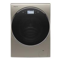
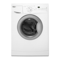
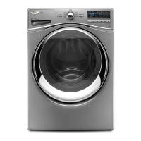
Shows visual representations of control panels for washer and combo models.
Procedure for testing LED indicators and buttons on the PCB.
Instructions for entering and performing factory inspection tests.
Faults related to water inflow and drainage problems.
Covers motor operation, door lock, and spin abnormalities.
Faults related to sensors, heating, and communication systems.
Troubleshooting general issues and understanding error codes.
Steps for removing external and control panel components.
Procedures for removing main body parts like front cover, filter, and drying duct.
Steps for removing internal parts such as the motor, pump, and drum.
Notes on the separate location and feeding of control and drive boards.