IV .structre
1. Structure diagram (see assembling drawing)
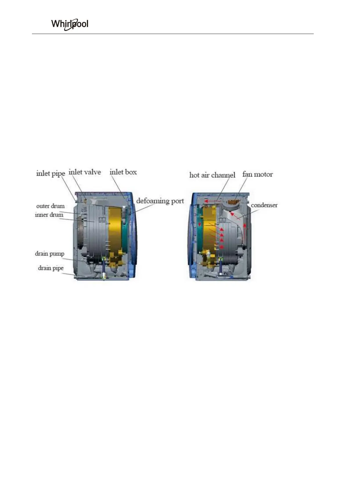
2. Water line system
Water inflow: inlet pipe - → inlet valve - → inlet box - → outer drum
Drainage: inner drum · outer drum - → water pump - → drainage pipe
Defoaming: inlet pipe - → inlet valve - → defoaming port - → inner drum · outer drum
Dehumidification: inlet pipe - → inlet valve - → condensate water pipe - → dehumidification pipe
- → outer drum - → drain valve - → inner drain pipe
Schematic diagram is as follows: (see attached drawings, only for drying models)
3. Hot air path
Fan motor―→Hot air channel―→drum―→condenser―→Fan motor