Do you have a question about the White Rodgers 1C20 and is the answer not in the manual?
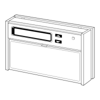
Instructions for removing the old thermostat's cover, base, and subbase.
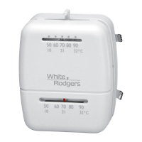
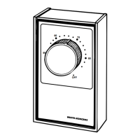
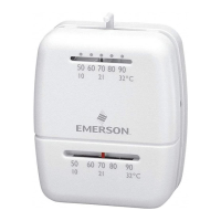
Instructions for mounting and wiring the 1C20 heat-only thermostat.
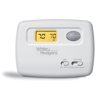
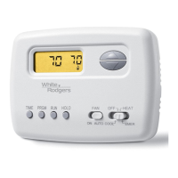
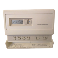
Instructions for mounting and wiring the 1C26 heating and cooling thermostat.
Instructions for mounting the thermostat base to the sub-base.
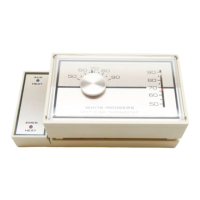
How to adjust the heat anticipator pointer for optimal heating cycles.
Common issues and corrective actions for no heating, cooling, or fan operation.
This document describes the installation and operation of White-Rodgers 1C20 (Heating only) and 1C26 (Heating & Cooling) thermostats. These thermostats are designed to replace various standard heating and cooling systems, including those with 4 or 5 wires, heat-only systems, millivolt floor or wall furnaces, standard central air conditioning, gas or oil heat, electric furnaces, and hydronic (hot water) zone heat systems. They are not suitable for heat pump systems with auxiliary or emergency heat, or for baseboard electric heating or line voltage (120 or 240 Volt) systems.
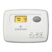
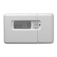
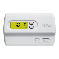
The White-Rodgers 1C20 and 1C26 thermostats serve as control units for residential heating and/or cooling systems. The 1C20 model is designed exclusively for heating applications, while the 1C26 model handles both heating and cooling. They regulate room temperature by switching the heating or cooling equipment on and off based on user-defined settings. The 1C26 model also includes a fan control feature, allowing users to set the fan to run automatically with the system or continuously.
Before installation, it is crucial to disconnect electrical power to the system at the main fuse or circuit breaker to prevent electrical shock and equipment damage. The installation process involves several steps:
The manual includes a comprehensive troubleshooting section to help users diagnose and resolve common issues. This section lists various symptoms, possible causes, and corrective actions:
The manual emphasizes safety warnings throughout, particularly regarding electrical shock and property damage if instructions are not followed. It also highlights the importance of proper disposal for old thermostats containing mercury.
| Type | Mechanical |
|---|---|
| Temperature Range | 50°F to 90°F (10°C to 32°C) |
| Display | Analog |
| Voltage | 24 VAC |
| Stages | 1 |
| Mounting | Wall |
| Compatibility | Single-stage heating and cooling systems |
| Accuracy | ±2°F |