EN
14139245.01 12/2015 EN/DE
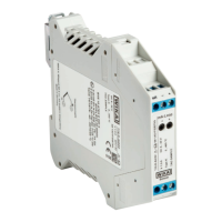
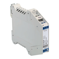
WIKA operating instructions model T1528
10.1 Safety-related characteristic values for models T15.x-AI, T15.x-AC
Intrinsically safe connection values for the current loop (4 ... 20 mA)
Level of protection Ex ia IIC/IIB/IIA, Ex ia IIIC or Ex ic IIC/IIB/IIA
Parameters Models T15.x-AI, T15.x-AC Model T15.x-AI
Gas hazardous application Dust hazardous
application
Terminals + / - + / -
Voltage U
i
DC 30 V DC 30 V
Current l
i
130 mA 130 mA
Power P
i
800 mW 750/650/550 mW
Effective internal capacitance C
i
18.4 nF 18.4 nF
Effective internal inductance L
i
20 µH 20 µH
Sensor circuit
Parameters Model T15.x-AI Model T15.x-AC
Ex ia IIC/IIB//IIA
Ex ia IIIC
Ex ic IIC/IIB//IIA
Terminals 1 - 4 1 - 4
Voltage U
o
DC 30 V DC 30 V
Current I
o
6.1 mA 6.1 mA
Power P
o
46 mW 46 mW
Max. external
capacitance C
o
IIC 30 nF
1)
180 nF
1)
IIB IIIC 0.520 µF
1)
1.37 µF
1)
IIA 1.70 µF
1)
5.40 µF
1)
Max. external
inductance L
o
IIC 1 mH 2 mH
IIB IIIC 1 mH 2 mH
IIA 1 mH 2 mH
Characteristics Linear
Notes:
U
o
: Maximum voltage of any conductor against the other three conductors
I
o
: Maximum output current for the least favourable connection of the internal current limiting resistors
P
o
: U
o
x I
o
divided by 4 (linear characteristic)
1) Internal L and C is already taken into account
Due to separation requirements of the applied standards, IS supply- and signal-circuit and
the IS sensor circuit shall be considered as being galvanically connected to each other.
The electrical parameters of the head and rail mounting versions are identical.
10. Specifications
 Loading...