EN
14
WIKA operating instructions, models TRxx and TCxx
14150915.08 04/2024 EN/DE/FR/ES
5. Commissioning and operation
5.1 Mechanical mounting
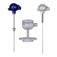
5.1.1 Multipoint thermometers
They are usually equipped with a case in which transmitters or terminal blocks are
mounted.
The transmitters/digital indicators are fastened mechanically (e.g. rail system in case or
holder in connection head).
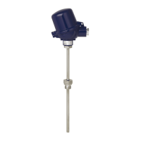
5.1.2 Cable probes
These are generally not fitted with a case. They can, however, be connected in an
additional case in which transmitter or terminal blocks are mounted.
5.1.3 Parallel threads
If the thermometer connection head, neck tube, thermowell/protection tube or process
connection are connected with parallel threads (e.g. G ½, M20 x 1.5 ...), these threads
must be secured using seals which prevent liquids from penetrating into the thermome-
ter.
As standard, WIKA uses copper seals for the connection between the neck tube and the
thermowell/protection tube, and a paper flat gasket for the connection of the connection
head and the neck tube or thermowell/protection tube.
If the thermometer and the thermowell/protection tube are already connected, the seals
will already be mounted (if ordered). The plant operator must check whether the seals
are suitable for the operating conditions and must replace them, if necessary, with suita-
ble seals, see chapter 10 “Accessories”.
Seals must be replaced after dismounting.
5.1.4 Tapered threads
With NPT or other tapered threads, it should be checked whether it may be necessary
to seal them additionally with PTFE tape or hemp. The threads must be lubricated with a
suitable lubricant before fitting.
5.2 Electrical mounting
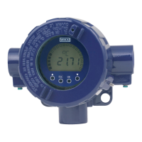
Using a transmitter/digital indicator (option):
Observe the contents of the operating instructions for the transmitter/digital indicator,
see scope of delivery.
Cable glands
Requirements for meeting ingress protection:
■
Only use cable glands within their indicated clamping area (cable diameter suitable
for the cable gland).
■
Do not use the lower clamping area with very soft cable types.
■
Preferably use round cables (if necessary, slightly oval in cross-section).
■
Do not twist the cable.
 Loading...