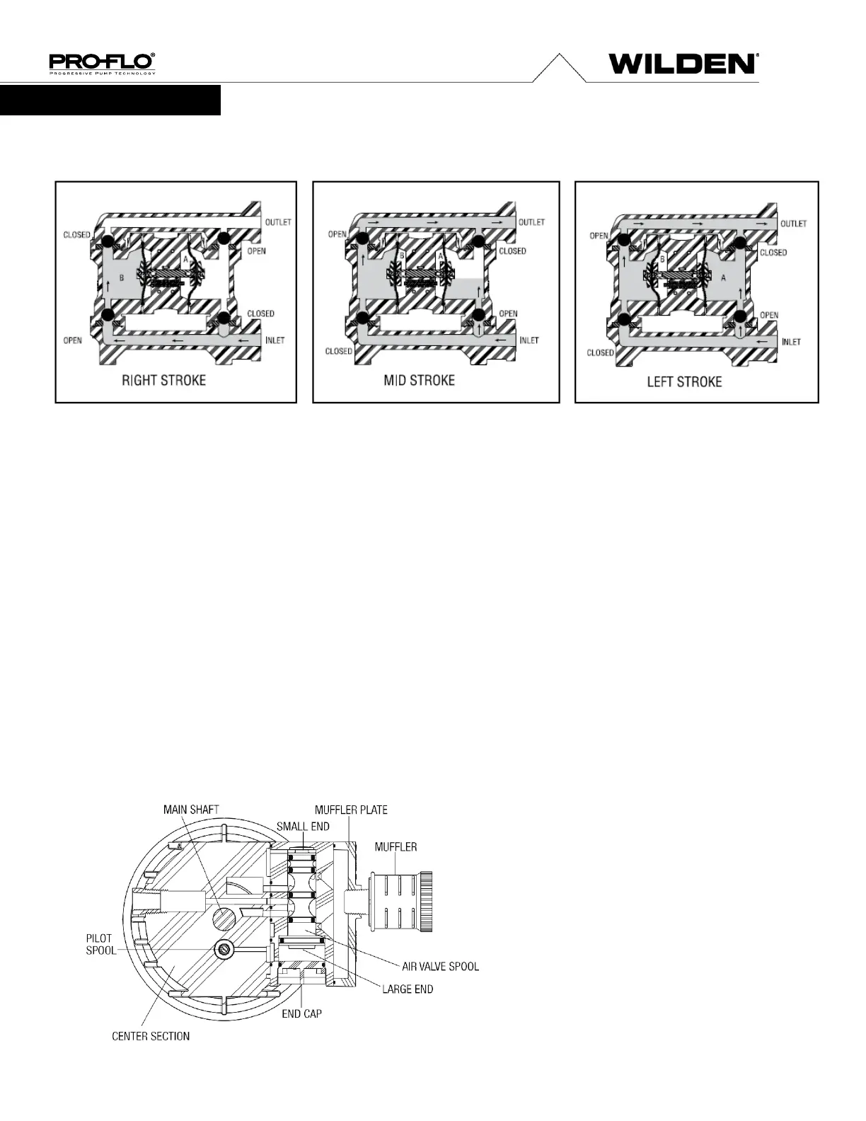
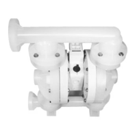
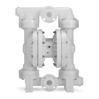
The Wilden diaphragm pump is an air-operated, positive displacement, self-priming pump. These drawings show the flow
pattern through the pump upon its initial stroke. It is assumed the pump has no fluid in it prior to its initial stroke.
FIGURE 1
The air valve directs pressurized
air to the back side of diaphragm A. The
compressed air is applied directly to the liquid
column separated by elastomeric
diaphragms. The diaphragm acts as a
separation membrane between the
compressed air and liquid, balancing the load
and removing mechanical stress from the
diaphragm. The compressed air moves the
diaphragm away from the center section of
the pump. The opposite diaphragm is pulled
in by the shaft connected to the pressurized
diaphragm. Diaphragm B is on its suction
stroke; air behind the diaphragm has been
forced out to the atmosphere through the
exhaust port of the pump. The movement of
diaphragm B toward the center section of the
pump creates a vacuum within chamber B.
Atmospheric pressure forces fluid into the
inlet manifold forcing the inlet valve ball off its
seat. Liquid is free to move past the inlet
valve ball and fill the liquid chamber (see
shaded area).
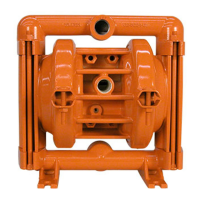
FIGURE 2
When the pressurized diaphragm,
diaphragm A, reaches the limit of its discharge
stroke, the air valve redirects pressurized air to
the back side of diaphragm B. The pressurized
air forces diaphragm B away from the center
section while pulling diaphragm A to the center
section. Diaphragm B is now on its discharge
stroke. Diaphragm B forces the inlet valve ball
onto its seat due to the hydraulic forces
developed in the liquid chamber and manifold
of the pump. These same hydraulic forces lift
the discharge valve ball off its seat, while the
opposite discharge valve ball is forced onto its
seat, forcing fluid to flow through the pump
discharge. The movement of diaphragm A
toward the center section of the pump creates
a vacuum within liquid chamber A.
Atmospheric pressure forces fluid into the inlet
manifold of the pump. The inlet valve ball is
forced off its seat allowing the fluid being
pumped to fill the liquid chamber.
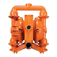
FIGURE 3
At completion of the stroke,
the air valve again redirects air to the
back side of diaphragm A, which starts
diaphragm B on its exhaust stroke. As
the pump reaches its original starting
point, each diaphragm has gone through
one exhaust and one discharge stroke.
This constitutes one complete pumping
cycle. The pump may take several cycles
to completely prime depending on the
conditions of the application.
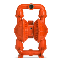
HOW IT WORKS — AIR DISTRIBUTION SYSTEM
The Pro-Flo
®
patented air distribution system incorporates three
moving parts: the air valve spool, the pilot spool, and the main
shaft/diaphragm assembly. The heart of the system is the air
valve spool and air valve. This valve design incorporates an
unbalanced spool. The smaller end of the spool is pressurized
continuously, while the large end is alternately pressurized then
exhausted to move the spool. The spool directs pressurized air
to one air chamber while exhausting the other. The air causes
the main shaft/diaphragm assembly to shift to one side —
discharging liquid on that side and pulling liquid in on the other
side. When the shaft reaches the end of its stroke, the inner
piston actuates the pilot spool, which pressurizes and exhausts
the large end of the air valve spool. The repositioning of the air
valve spool routes the air to the other air chamber.