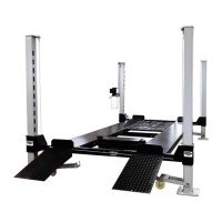
Step 2: LAYOUT AND POWER UNIT LOCATION
Before you begin your assembly, you will want to determine where your lift will be
located and the orientation of your power unit. The top runway as packaged contains the
hydraulic ram responsible for raising and lowering your lift. At the end of this runway
there is a hole where the hydraulic hose from the hydraulic ram will be inserted and
fastened in place. This is the corner where the power unit will be located. This means
that you can located the power unit in one of the starred locations shown below. Based
on the corner you choose will determine how you will need to orient the runway with the
hydraulic ram. Note: The runway with the hydraulic ram will always be located on the
same side as the power unit.
Once you determine your power unit location make sure as you move to assembly that
you pay attention to correct orientation of your runways and crossbeams.
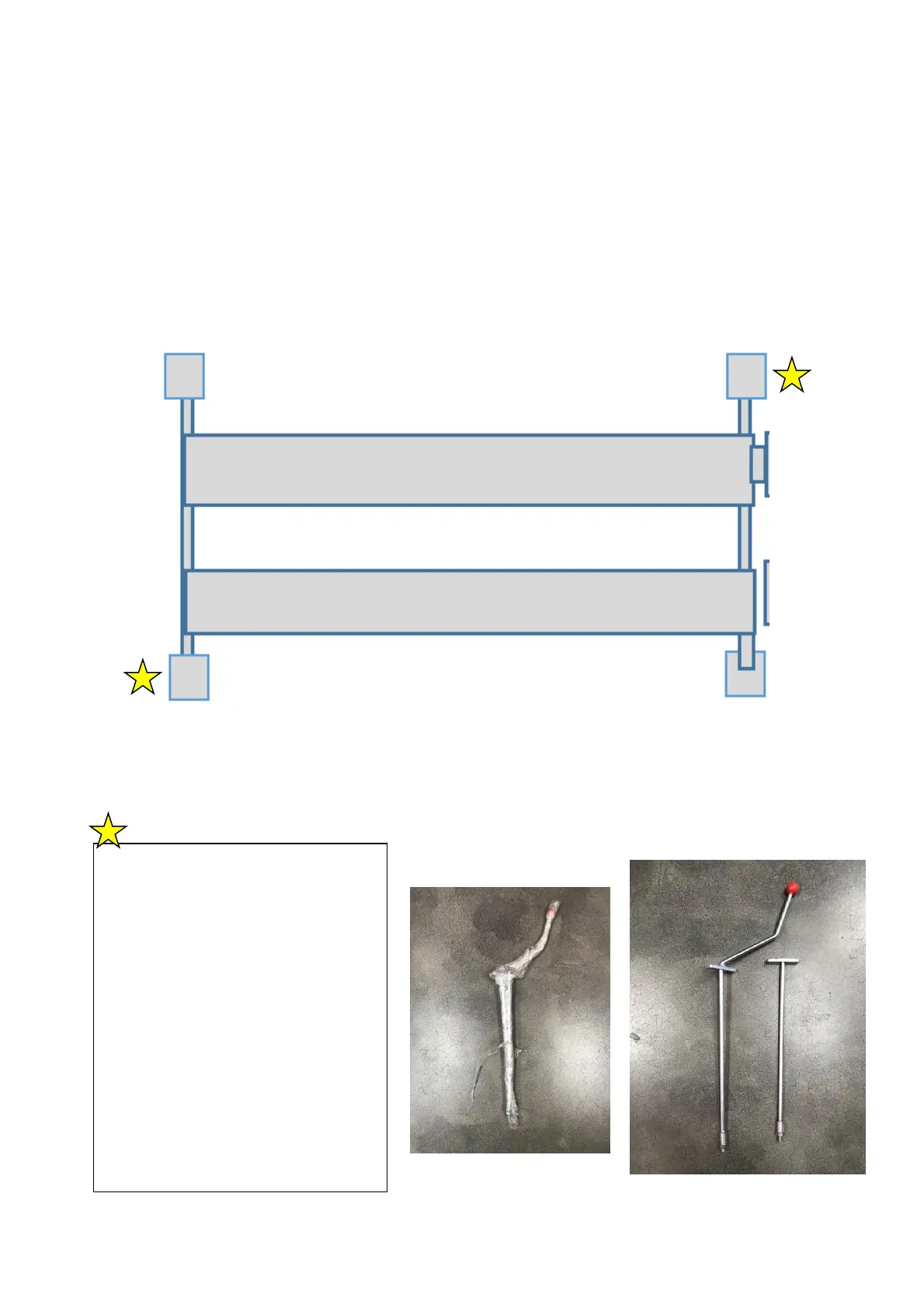
Ensure you leave yourself
enough room on the front/back
of the lift to allow the linkage
rods to be slide into the
crossbeam once the lift has
been set up. You can find this
step further down into the
guide but will need to make
sure you give yourself room
now before getting to that
step. The photos to the right
→ are the pieces you will need
to account for.