EasyManua.ls Logo

Wildfire WF9000 - User Manual

Wildfire WF9000
30 pages
Print Icon
To Next Page IconTo Next Page
Loading...
INSTALLATION & OPERATION MANUAL
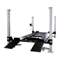
9000lb. Capacity Models:WF9000
4 Post Parking Lift WF9000XLT
SHIPPING DAMAGE CLAIMS
When this equipment is shipped, title passes to the purchaser upon receipt from the carrier. Consequently,
claims for the material damaged in shipment must be made by the purchaser against the transportation
company at the time shipment is received.
BE SAFE
Your new lift was designed and built with safety in mind. However, your overall safety can be increased
by proper training and thoughtful operation on the part of the operator. DO NOT operate or repair this
equipment without reading this manual and the important safety instructions shown inside.
Keep this operation manual near the machine at all times. Make sure that ALL USERS read this manual

Questions and Answers

Summary

Wildfire Lifts Manual Introduction and Safety

Shipping Damage Claims Procedure

Procedures for reporting damage incurred during shipping.

Essential Lift Operation Safety

Crucial safety warnings and advice for lift operation.

Product Specifications and Warranty Information

Recording Lift Serial and Model Numbers

Section to record lift serial number, model, and manufacturing date.

Wildfire Lift Warranty Coverage

Details on the warranty coverage for lift structure and hydraulics.

Lift Model Weight Capacity

Table listing the rated maximum load for different lift models.

Manual Overview and Preparation

Manual Introduction and Scope

Brief overview of the manual's purpose and content.

Critical Safety Warnings and Procedures

Critical safety warnings and operating procedures to prevent injury.

Assembly Tool Requirements

List of tools required for the lift's assembly process.

Installation Site and Setup

Selecting Installation Site and Clearance

Guidelines for choosing an installation location, considering space and overhead clearance.

Floor Requirements for Installation

Specifications for the concrete floor needed for safe and proper lift installation.

Packing, Transport, and Storage Guidelines

Procedures for handling the lift during transport, unpacking, and storage.

Lift Technical Details and Components

Hydraulic Fluid Type and Quantity

Specifies the type and quantity of hydraulic fluid needed for the lift.

Lift Package Contents List

Itemizes all components included in the lift package.

Assembly Instructions: Step-by-Step Guide

Step 1: Unpacking and Parts Verification

Detailed steps for unpacking the lift and verifying all parts are present.

Step 2: Layout and Power Unit Placement

Guidance on determining the lift's placement and power unit orientation.

Step 3: Upright Columns and Crossbeams

Detailed steps for assembling upright columns and crossbeams.

Step 4: Runway Installation

Procedures for positioning and securely attaching the lift runways.

Step 5: Cable Routing and Connection

Instructions for routing and connecting lift cables to the posts.

Step 6: Safety Linkage Installation

Steps for connecting and adjusting the lift's safety linkage system.

Step 7: Pulley Cover Installation

Guidance on attaching protective covers to the lift's pulleys.

Step 8: Power Unit Mounting

Instructions for mounting the hydraulic power unit onto the lift structure.

Step 9: Accessory Installation

Steps for installing optional accessories like wheel stops and jack trays.

Operation and Maintenance Procedures

Safely Raising and Lowering the Lift

Detailed instructions for safely raising and lowering the vehicle lift.

Caster Usage for Lift Mobility

Guide on how to install and use casters for moving the lift.

Recommended Monthly Maintenance

Recommended monthly checks to ensure the lift's safe operation and longevity.

Critical Lift Operation Warnings

Key warnings regarding lift capacity, component condition, and safe operation zones.

Troubleshooting, Diagrams, and Parts

Troubleshooting Common Lift Problems

Guide to identify and resolve common problems with the lift's operation.

Hydraulic System Diagram Explained

Visual representation of the lift's hydraulic components and flow.

Lift Exploded Part Views

Illustrated breakdown of lift components with part numbers for reference.

Complete Lift Parts List

A detailed list of all parts included with the lift, including quantities.

Cable Assembly Illustrated Guide

Diagrammatic guide for assembling the lift's cable system.

Overview

This document is an installation and operation manual for the Wildfire Lifts 9000lb. Capacity 4 Post Parking Lift, including models WF9000 and WF9000XLT.

Function Description:

The Wildfire 4 Post Parking Lift is designed to raise and lower vehicles, providing additional storage space in garages or other suitable locations. It is intended for storing cars and trucks, with a focus on quality construction and aesthetic appeal to complement the user's space. The lift operates hydraulically, using a power unit to raise and lower the runways, which are supported by four upright columns. Safety features, including locking mechanisms and linkage rods, are integrated to ensure secure operation.

Important Technical Specifications:

  • Capacity: 9,000 pounds (WF9000 and WF9000XLT models). Other models listed include WF7500TL (7,500 lbs) and WF10000DW (10,000 lbs).
  • Total Column Height: 91.81 inches (WF9000) / 101.69 inches (WF9000XLT).
  • Lifting Time: 60-90 seconds (may vary based on total loaded weight).
  • Maximum Lifting Height: 78 inches (WF9000) / 86.6 inches (WF9000XLT).
  • Motor Power: 2.2 kW.
  • Working Voltage: 120V 20Amp.
  • Noise Level: ≤70dB(A).
  • Oil Pressure: 20MPa.
  • Hydraulic Fluid: Requires 2.6 gallons (10.5 quarts) of AW-32 or ISO-32 hydraulic fluid. DEXRON® is explicitly not to be used.
  • Power Unit Electrical Requirements: A 20amp circuit running on a 12 gauge wall wire or extension cord is required. Lighter duty wiring can damage the motor. GFCI on the electrical run may need to be removed to allow the motor to draw the initial start-up amperage.
  • Floor Requirements: Must be installed on a solid, level concrete floor with no more than 2 degrees of slope. The concrete should be a minimum of 3-1/2 inches thick, 3500psi, steel reinforced. Not suitable for asphalt, wood, or other non-specified surfaces.
  • Rolling Bridge Jack Capacity: 3,000 lbs (if equipped).

Usage Features:

  • Installation Site Selection: Users must ensure adequate space for the assembled lift, considering length, width, and height, and freedom from overhead obstructions.
  • Power Unit Placement: The power unit can be located in one of two "starred" corners (front left or rear right) of the lift, which determines the orientation of the runway with the hydraulic ram.
  • Safety Linkage System: The lift incorporates safety linkage rods that connect to a black linkage rod under the runway. These are adjusted to ensure proper engagement of the safety locks.
  • Safety Locks: The lift has main safety locks and secondary top locks. During operation, it's crucial to ensure all four locks are engaged when the lift is elevated.
  • Raising the Lift: Drive the vehicle onto the platform, engage park/gear, set the parking brake, chock wheels, and remove approach ramps. Press the power button to raise to the desired height, then release the power button. Lower the lift onto the safety latches using the release lever.
  • Lowering the Lift: Ensure the area is clear. Raise the lift slightly to disengage safety latches. Pull down the release handle and simultaneously press the release lever on the power unit to lower the lift. The release lever must be held open throughout the lowering process.
  • Caster Kit (Optional): A caster kit allows the lift to be moved. It consists of 4 casters (2 left, 2 right), 4 pins, washers, and hairpins. When moving, two people are recommended, and the floor must be clear of obstructions. The casters are installed with the long straight edge towards the inside of the lift.
  • Approach Ramps: Can be used from either end of the lift. It is recommended to remove them before raising the lift.
  • Rolling Jack Tray: Installed by loosening axles with an allen wrench, aligning grooves with the runway channel, and centering the wheels. Locks are then assembled to hold the tray when engaged.
  • Drip Trays: Three large plastic drip trays can be placed on the center channels between the runways to provide protection below.

Maintenance Features:

  • Shipping Damage Claims: Purchasers are responsible for reporting shipping damage to the carrier upon receipt.
  • Regular Inspection: Before operation, inspect for concealed shipment damage or shortages.
  • Cleanliness: Keep the lift clean, free from grease, oil, trash, and other debris for better and safer performance. Keep control handles/buttons dry and clean.
  • Damaged Parts Check: Regularly check for damaged parts, breakage, or any condition affecting operation. Do not use the lift if components are broken or damaged.
  • Safety Component Integrity: Never remove safety-related components. Do not use the lift if safety components are damaged or missing.
  • Electrical Safety: Turn off power before performing any electrical repairs. The power unit contains high voltage.
  • Monthly Maintenance:
    • Check safety locks for good operating condition.
    • Check all cables for excessive signs of wear.
    • Perform a visual inspection of all moving parts for wear.
    • Replace faulty parts before resuming operation.
  • Cable Adjustment: Instructions for adjusting cables are provided in the operation portion of the manual.
  • Troubleshooting Guide: A comprehensive guide is included to address common issues such as the pump/motor not starting, operating with no pressure, low flow/pressure, not holding the system, failure to lower, air in oil, oil blowing out the breather/filter port, cylinder not lifting load, and motor "clicking" on start-up. Solutions range from rewiring and replacing fuses to adjusting valves and replacing seals.
  • Air Purging: When pulling cables into position, air will be sucked into the cylinder. This air is removed on the first use by slowly lowering the lift to push air out into the reservoir, preventing vapor locking.

Wildfire WF9000 Specifications

General IconGeneral
BrandWildfire
ModelWF9000
CategoryLighting Equipment
LanguageEnglish

Related product manuals