Installation en
Installation and operating instructions Wilo-Control MS-L 25
3
Control MS-L2...
SSM Alarm
Fig.15: Terminal strip sensors: external alarm
signal for high water
An external alarm signal (horn, flashing light, etc.) can be connected for the high water
alarm:
ƒ Contact type: potential-free changeover contact
ƒ Contact load:
– Minimum: 12VDC, 10mA
– Maximum: 250VAC, 1A
Insert the connection cables laid by the customer through the threaded cable glands
and secure. Connect the wires to the terminal strip according to the connection dia-
gram.
Switchgear Normally open contact
(NO)
Normally closed contact
(NC)
Control MS-L1...
− −
Control MS-L2...
Terminal 15/16 Terminal 14/15
6.6 Functions
The switchgear is equipped with the following functions. All functions are switched off
at the factory. The functions must be switched on as required.
Inputs/outputs
Control MS-L 1...
Control MS-L 1...-O
Control MS-L 1...-LS
Control MS-L 2...
Control MS-L 2...-O
Control MS-L 2...-LS
Internal buzzer
• • • • • •
Pump kick
• • • • • •
Service interval indicator
− − − • • •
Monitoring operating parameters
− − − • • •
Follow-up time
• • • • • •
Adjustable switching points for pump ON and high water*
− − • − − •
Key
• = available, − = not available
* The switching points can be selected from eight sets of parameters for the respective
lifting unit.
6.6.1 Internal buzzer
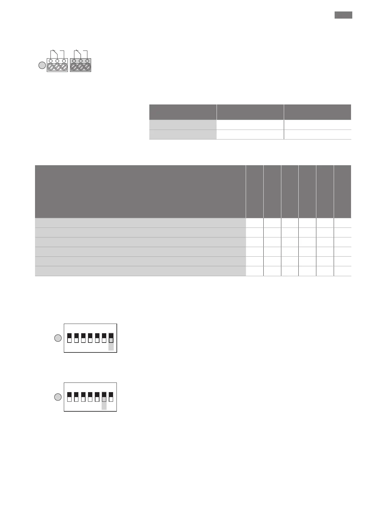
Fig.16: DIP switch1: internal buzzer
The internal buzzer can also issue audible warning messages in addition to the visual in-
dicator. Switch the internal buzzer on/off via DIP7 on DIP switch1:
ƒ “ON” position: Buzzer on
ƒ “OFF” position: Buzzer off
6.6.2 Pump kick
Fig.17: DIP switch1: Pump kick
To prevent prolonged standstill periods for the connected pumps, a periodic test run
can be performed (pump kick function). A 2s test run takes place after a standstill
period of 24h for the respective pump.
Switch the pump kick on/off via DIP6 on DIP switch1:
ƒ “ON” position: Pump kick on
ƒ “OFF” position: Pump kick off
6.6.3 Service interval indicator
A service interval indicator can be switched on to increase operational reliability. The
time is recorded continuously when the mains voltage is switched on. After the interval
has elapsed, a visual signal is emitted by means of the yellow LED on the front. NO-
TICE!There is no audible signal and the collective fault signal is not activated!