en Operation
26 WILO SE 2020-05
Fig.18: DIP switch2: Service interval indicator
Switch the desired interval on and off via DIPs4 and 5 on DIP switch2:
ƒ DIP4 and 5 “OFF”: Service interval off
ƒ DIP4 “ON”: ¼ year service interval
ƒ DIP5 “ON”: ½ year service interval
ƒ DIP4 and 5 “ON”: 1 year service interval
Contact customer service to reset the counter.
6.6.4 Monitoring operating parameters
The following operating parameters can be monitored on each pump to increase the
operational reliability:
ƒ Connections/h
ƒ Connections/d
ƒ Running time/h
If the factory-set parameters are exceeded, a visual signal is emitted via the yellow LED
on the front. NOTICE!There is no audible signal and the collective fault signal is not
activated!
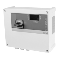
Fig.19: DIP switch2: Monitoring the operating
parameters
Switch the desired monitoring devices on and off via DIPs1 to 3 on DIP switch2:
ƒ DIP1: Connections/h
ƒ DIP2: Connections/d
ƒ DIP3: Running time/h
Contact customer service to reset the counter.
6.6.5 Follow-up time
The follow-up time defines the time between the float switch “OFF” signal and the
pump being deactivated by the switchgear. Adjust the follow-up time continuously at
the potentiometer.
Fig.20: Adjusting the follow-up time
Setting ranges
ƒ Control MS-L...: 0...120s
ƒ Control MS-L... -O: 0...120s
ƒ Control MS-L ... -LS: 0...30s
6.6.6 Set switching points (only Control
MS-L...-LS)
The switching points for the lifting unit are set at the factory. The switching points can
be adjusted to increase the usable volume. The switching points are stored in eight sets
of parameters. The sets of parameters are set via DIP switch3.
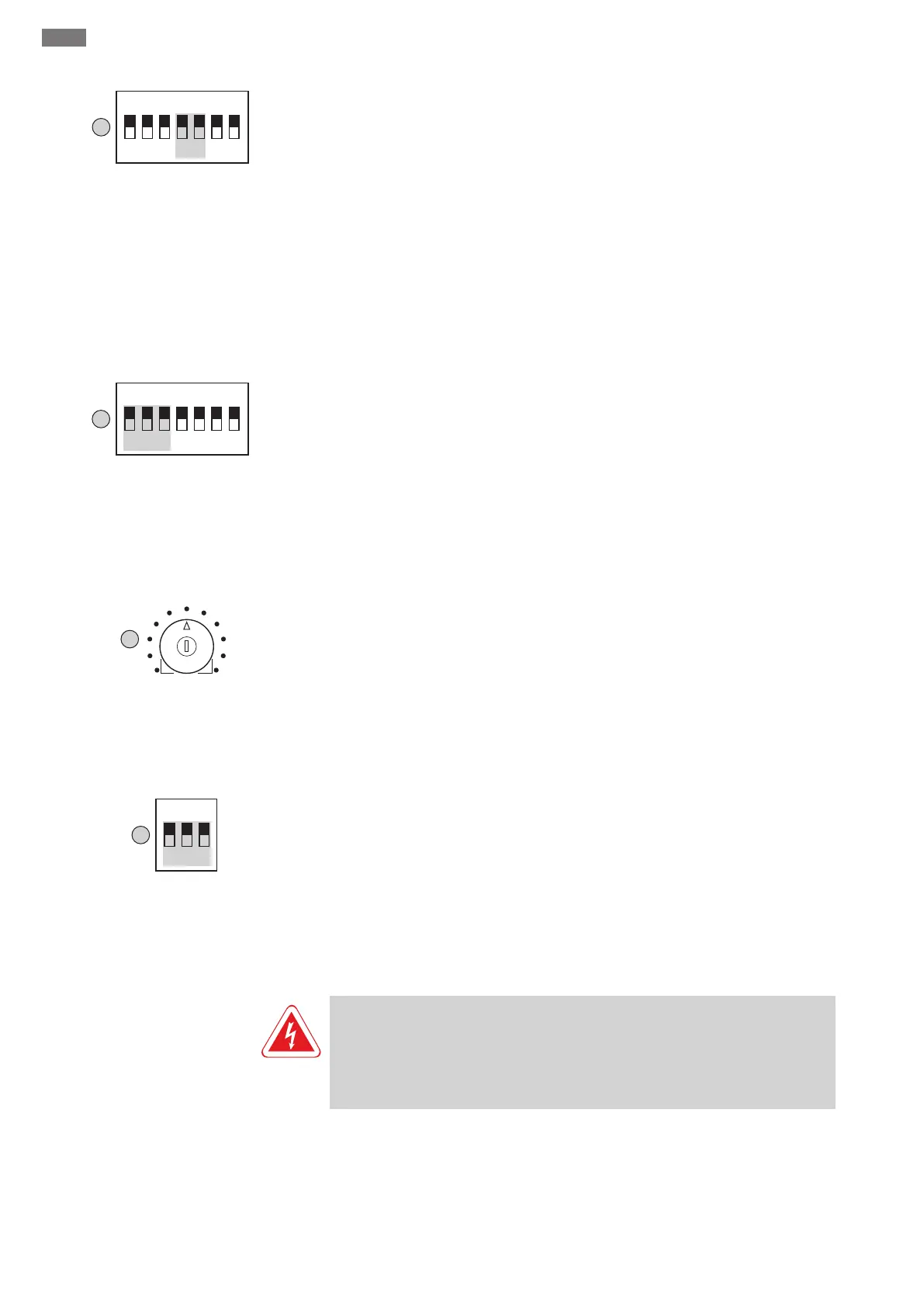
Fig.21: DIP switch3: setting the switching
points
NOTICE!Consult the sets of parameters in the installation and operating instruc-
tions for the respective lifting unit!
7 Operation
DANGER
Risk of fatal injury due to electrical current!
Only operate the switchgear when closed. There is a risk of fatal injury from open
switchgear! Electrical work on the internal components must be carried out by a
qualified electrician.
7.1 Operating elements
The switchgear is operated via the following operating elements:
ƒ Main switch
ƒ Buttons on the side control panel
ƒ LEDs on the front