Appendix en
Installation and operating instructions Wilo-Control MS-L 35
Please note the following points to ensure proper handling, recycling and disposal of
the used products in question:
ƒ Hand over these products at designated, certified collection points only.
ƒ Observe the locally applicable regulations!
Please consult your local municipality, the nearest waste disposal site, or the dealer who
sold the product to you for information on proper disposal. See
www.wilo‑recycling.com for more information about recycling.
13 Appendix
13.1 System impedances
NOTICE
Maximum switching frequency per hour
The connected motor determines the maximum switching frequency per hour. Note
the technical data of the connected motor! The maximum switching frequency of
the motor must not be exceeded.
NOTICE
• Depending on the system impedance and the maximum connections/hour of the
connected consumers, voltage fluctuations and/or drops may occur.
• When using shielded cables, attach the shielding to the earth rail on one side of the
switchgear!
• Always have connection carried out by a qualified electrician!
• Observe the installation and operating instructions for the connected pumps and
signal transmitters.
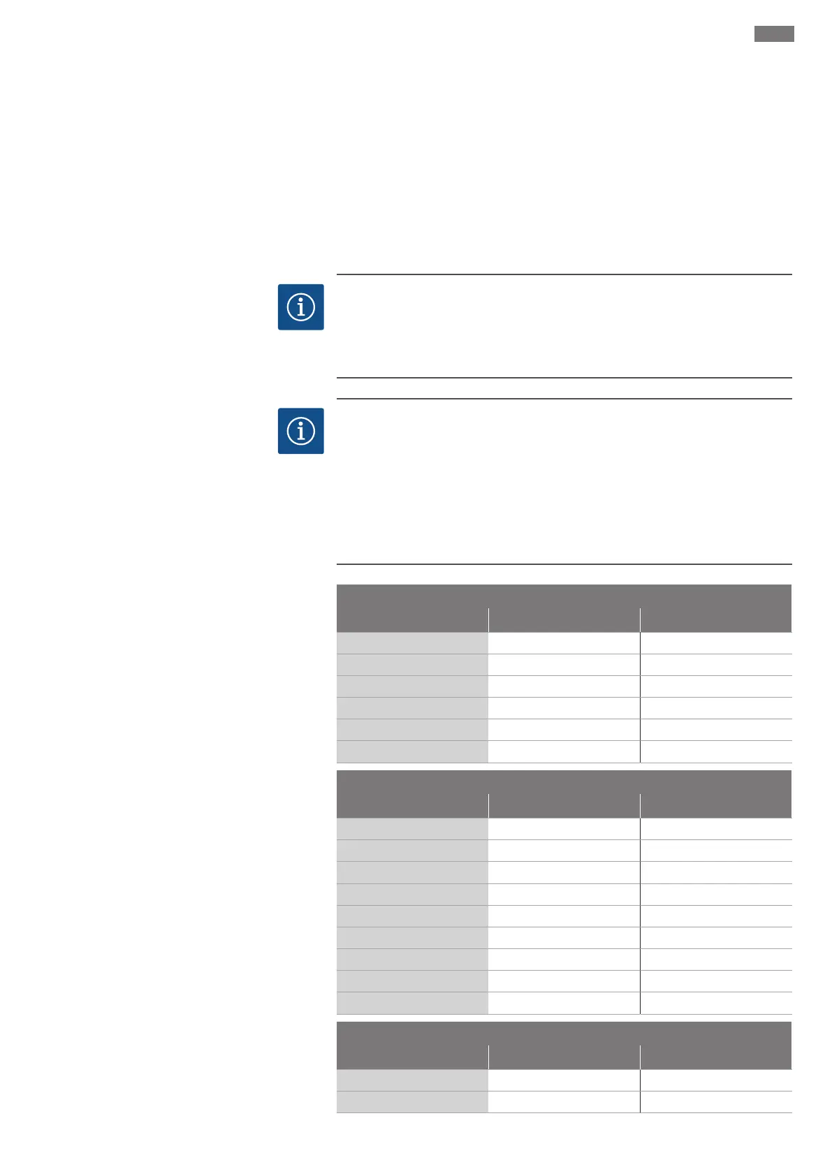
1~230V, 2-pole, direct starting
Power in kW System impedance in ohm Connections/h
1.5
0.4180 6
1.5
0.3020 24
1.5
0.2720 30
2.2
0.2790 6
2.2
0.1650 24
2.2
0.1480 30
3~400V, 2-pole, direct starting
Power in kW System impedance in ohm Connections/h
2.2
0.2788 6
2.2
0.2126 24
2.2
0.1915 30
3.0
0.2000 6
3.0
0.1292 24
3.0
0.1164 30
4.0
0.1559 6
4.0
0.0889 24
4.0
0.0801 30
3~400V, 4-pole, direct starting
Power in kW System impedance in ohm Connections/h
2.2
0.2330 24
2.2
0.2100 30