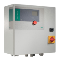
Installation and operating instructions Wilo-Control SC-L 39
OPERATION AND FUNCTION English
NOTE
• No external voltage may be applied!
• We recommend dry-running protection always
be provided as additional fuse protection for the
unit.
5.4.7. Connection of the high water alarm using a
separate oat switch
A high water alarm can be realised via a poten-
tial-freecontactusingaoatswitch.
Insert the cable ends of the cable laid on-site
through the threaded cable connections and
secure accordingly.
Connect the wires to the terminal strip according
to the wiring diagram.
• Contact:
• Closed:Highwateralarm
• Open:Nohighwateralarm
NOTE
• No external voltage may be applied!
• Werecommendoodcontrolalwaysbeprovid-
ed as additional fuse protection for the unit.
5.4.8. Connection of automatic mode remote activa-
tion and deactivation (External OFF)
Remote switching of automatic mode can be
realised via a potential-free contact. Using an
additionalswitch(e.g.aoatswitch)automatic
mode can be switched on and off as a result. This
function overrides all other switching points and
all pumps are switched off. The terminals are
ttedwithaconverterbridgeinthefactory.
Insert the cable ends of the cable laid on-site
through the threaded cable connections and
secure accordingly.
Remove the converter bridge and connect the
wires to the terminal strip according to the wiring
diagram.
• Contact:
• Closed:Automaticon
• Open:Automaticmodeoff-signalviaanicon
on the display
NOTE
No external voltage may be applied!
5.4.9. Connection of level actual value display
A0-10Vsignalisavailableforexternalmeas-
urement / display of the level actual value via the
correspondingterminals.Withthis0Visthelevel
sensorvalue“0”and10Vthelevelsensornal
value.
Example:
• Levelsensor2.5m
• Displayrange:0...2.5m
• Setting:1V=0.25m
Insert the cable ends of the cable laid on-site
through the threaded cable connections and
secure accordingly.
Connect the wires to the terminal strip according
to the wiring diagram.
NOTE
• No external voltage may be applied!
• To be able to use the function, the value “Sen-
sor” has to be set in menu 5.2.6.0.
5.4.10. Connection of collective run signal (SBM),
collective fault signal (SSM) or high-water alarm
(HW)
Potential-free contacts for external signals are
available via the corresponding terminals.
Insert the cable ends of the cable laid on-site
through the threaded cable connections and
secure accordingly.
Connect the wires to the terminal strip according
to the wiring diagram.
• Contact:
• Type:Changeovercontact
• Switchingcapacity:250V,1A
DANGER due to electrical voltage!
An external voltage is applied at the terminals
for this function. This is also present at the
terminals when the main switch is switched
off! There is a risk of fatal injury! The power
supply must be disconnected from its source
before all work!
5.4.11. Connection for activating/deactivating an ex-
ternal control
A potential-free contact is available via the corre-
sponding terminals for activating/deactivating an
external control. An external submersible mixer,
for instance, can be switched on with this.
Insert the cable ends of the cable laid on-site
through the threaded cable connections and
secure accordingly.
Connect the wires to the terminal strip according
to the wiring diagram.
• Contact:
• Type:Normallyopencontact
• Switchingcapacity:250V,1A
DANGER due to electrical voltage!
An external voltage is applied at the terminals
for this function. This is also present at the
terminals when the main switch is switched
off! There is a risk of fatal injury! The power
supply must be disconnected from its source
before all work!
6. Operation and function
This section contains all information on how the
switchgear functions as well as information on
the menu structure.

 Loading...