Installation and operating instructions Wilo-Control SC-L 41
OPERATION AND FUNCTION English
NOTE
In case of level measurement using a level
sensor, forced switch-on or switch-off only
takes place if dry-running protection and the
high water alarm are additionally realised with a
oatswitch!
6.2. Menu control and structure
6.2.1. Control
Fig. 6: Operation
Themenuiscontrolledviatheoperatingknob:
• Turn:Selectionandsetvalues
• Press:Changemenulevelorconrmvalue
6.2.2. Set-up
Themenuisdividedintotwoareas:
• Easy menu
For quick commissioning using the factory set-
tings, only the operating mode and the activation
and deactivation values need to be set here.
• Expert menu
For display and setting of all parameters.
Open menu
1. Press operating knob for 3 seconds.
2. Menu item 1.0.0.0 appears.
3. Turnoperatingknobtoleft:Easymenu
Turnoperatingknobtoright:Expertmenu
6.3. Initial commissioning
NOTE
Observe the installation and operating in-
structionsforproductsprovidedon-site(oat
switches, level sensors, connected consumers)
as well as the system documentation!
The following points must be checked before the
initialstart-up:
• Check the installation.
• All terminals must be retightened.
• Motor protection correctly set.
• The separate HAND-0-AUTO switch for each
pump must be set to “AUTO (A)”. The factory
setting for these is “0 (OFF)”!
Switching on
1. Turn main switch to ON position.
2. The display lights up and outputs the latest
information. The display appearance changes
dependingonthesignaltransmitterconnected:
3. The “Standby” symbol appears and the switch-
gear is ready for operation. You can now set the
individual operating parameters.
NOTE
IftheredfaultLEDlightsuporashesimme-
diately after activation, observe the error code
information on the display!
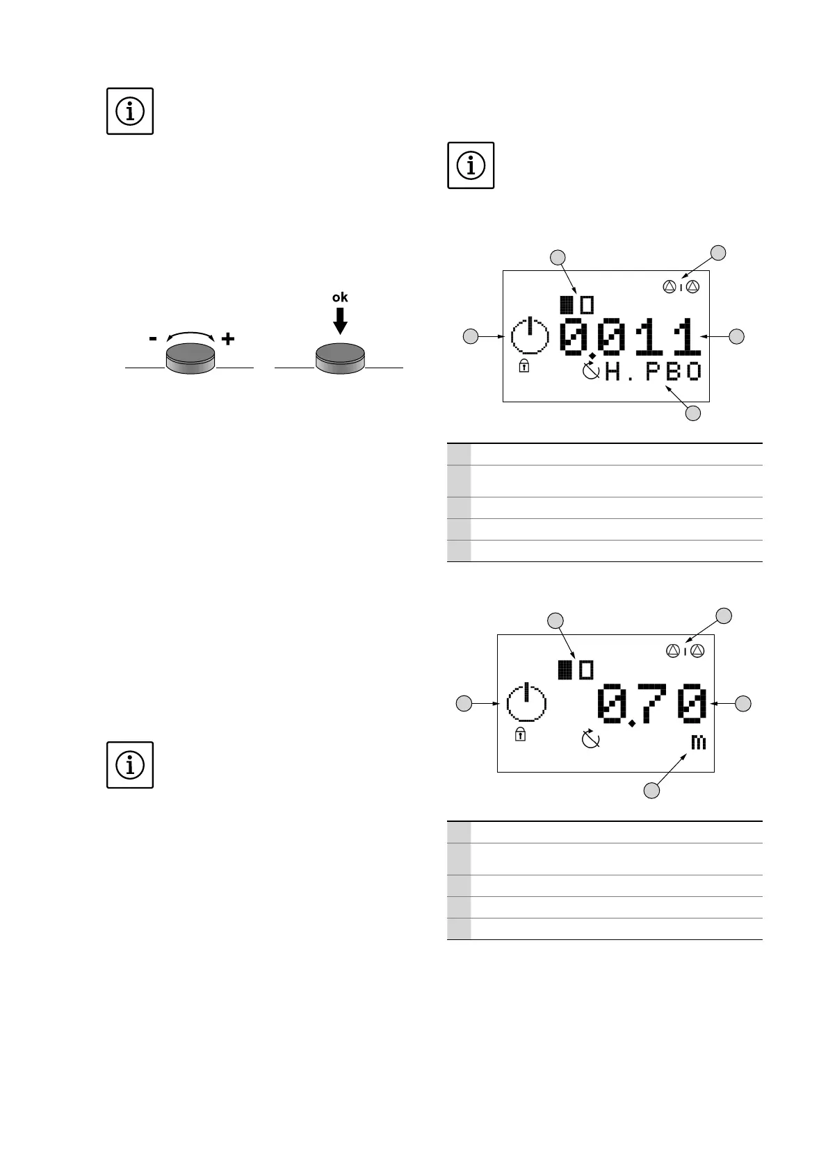
Fig. 7: Appearance of display with oat switch
1
2
3
4
5
1 Control with standby pump
2
Currentpumpstatus:Numberofregisteredpumps/
pump on/pump off
3 Switchingstateoftheindividualoatswitches
4 Float switch designation
5 Area for the display of graphical symbols
Fig. 8: Appearance of display with level sensor
1
2
3
4
5
1 Control with standby pump
2
Currentpumpstatus:Numberofregisteredpumps/
pump on/pump off
3 Currentlllevel
4 Unit of value currently displayed
5 Area for the display of graphical symbols
6.4. Setting the operating parameters
Themenuisdividedintosevenareas:
1. Control parameters (operating mode, start/stop
delays)
2. Communicationparameters(eldbus)
3. Pump activation (activation and deactivation of
the connected pumps)