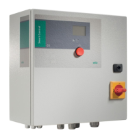
Installation and operating instructions Wilo-Control SC-L 51
APPENDIX English
Switching cycles of pump 3
Switching cycles of pump 4
Communication
Communication parameters
Output parameters
Collective run signal (SBM) parameter
Collective fault signal (SSM) parameter
ModBus
BACnet
GSM modem
Dry run
Switching threshold for dry run signal.
Delay time (restart after dry run)
Follow-up time in event of dry run
High water
Switching threshold for high water signal
Delay time (up to triggering of high water)
Base-loadpump:Activationthreshold
Base-loadpump:Deactivationthreshold
Base-loadpump:Delaytimedeactivation
Peak-loadpump1:Activationthreshold
Peak-loadpump2:Activationthreshold
Peak-loadpump3:Activationthreshold
Peak-loadpump:Delaytimeforactivation
Peak-loadpump1:Deactivationthreshold
Peak-loadpump2:Deactivationthreshold
Peak-loadpump3:Deactivationthreshold
Peak-loadpump:Delaytimedeactivation
System restart delay time
11.2. System impedance tables
System impedances for 3~400V, 2-pole, direct starting
Power System impedance Connections/h
kW ohms
2.2 0.257 12
2.2 0.212 18
2.2 0.186 24
2.2 0.167 30
3.0 0.204 6
3.0 0.148 12
3.0 0.122 18
3.0 0.107 24
4.0 0.130 6
4.0 0.094 12
4.0 0.077 18
5.5 0.115 6
5.5 0.083 12
5.5 0.069 18
7.5 0.059 6
7.5 0.042 12
9.0 – 11.0 0.037 6
9.0 – 11.0 0.027 12
15.0 0.024 6
15.0 0.017 12
System impedances for 3~400V, 2-pole, star-delta
starting
Power System impedance Connections/h
kW ohms
5.5 0.252 18
5.5 0.220 24
5.5 0.198 30
7.5 0.217 6
7.5 0.157 12
7.5 0.130 18
7.5 0.113 24
9.0 – 11.0 0.136 6
9.0 – 11.0 0.098 12
9.0 – 11.0 0.081 18

 Loading...