32
English
DANGER! Risk of property damage!
The converter cover must not be forced closed.
• Carefully place the connectors inside the con-
verter before closing.
Information about electrical connections
Unscrew the screws and remove the top cover
from the converter.
- The electric characteristics (frequency, voltage,
nominal current) of the frequency converter
are specified on the pump identification label.
Ensure that the frequency converter complies
with the mains supply used.
- The electric protection of the motor is integrated
into the converter. The parameters must comply
with the pump characteristics and must ensure
the protection of pump and motor.
- In case of impedance between earth and neutral
point, install a protection device upstream of the
frequency converter.
- Provide a fused isolation switch (type gF) to pro-
tect the mains installation.
NOTE: If a differential circuit breaker needs to be
installed for the user’s protection, it must have
a delay effect. Adjust the circuit breaker rating
according to the current provided on the pump
identification sticker.
NOTE: This pump is equipped with a frequency
converter and does not require protection from a
residual-current operated device.
Frequency converters can impair the function of
residual-current-operated device.
Exception:
Residual-current operated devices that have a
selective universal-current-sensitive design are
permitted.
• Labelling: RCD
• Trigger current: > 30 mA.
- Use only power cables complying with applicable
regulations.
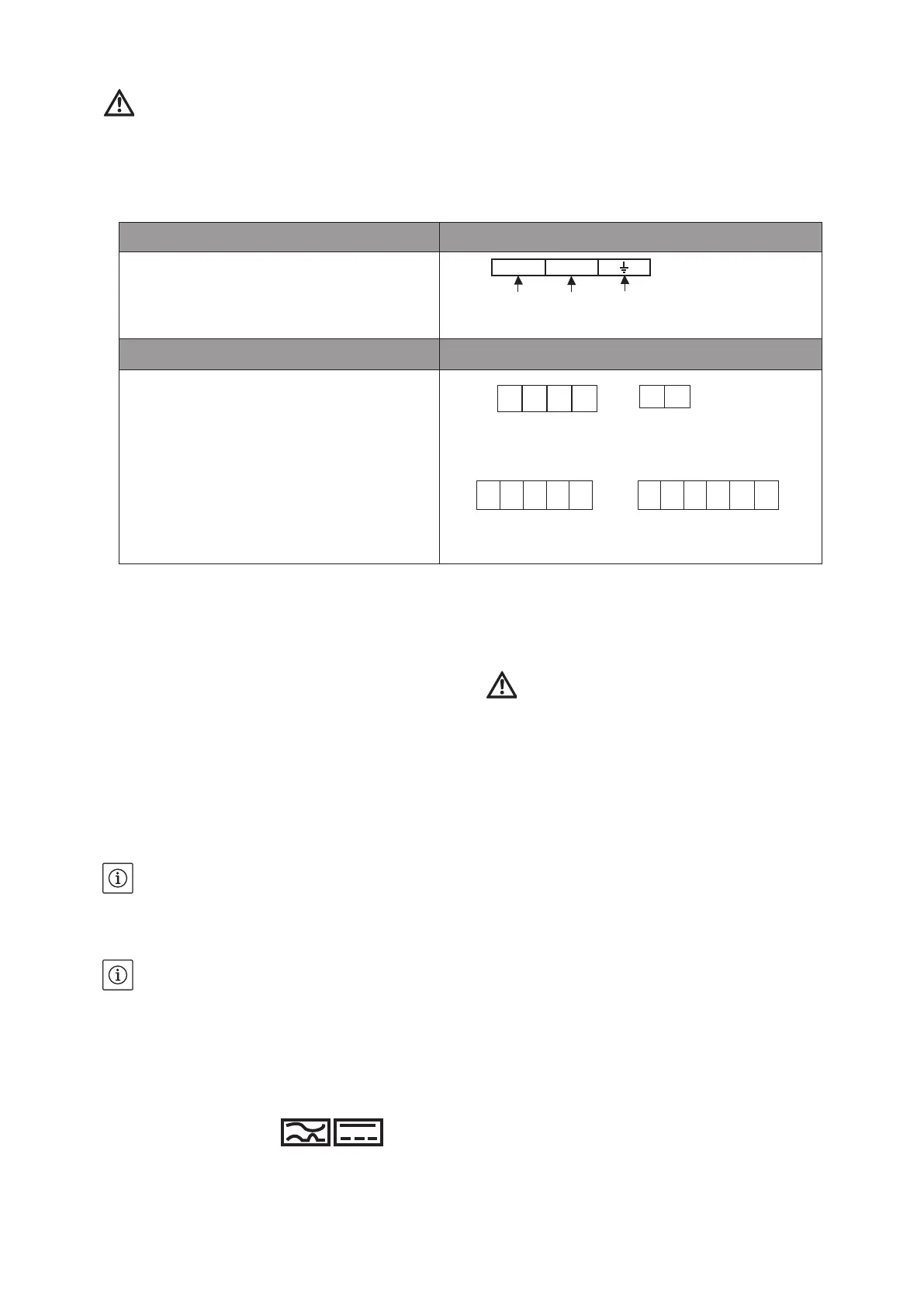
Connection to mains supply Power terminals
Connect the 3-wire cable to the power terminals
(phases + earth).
Fig. A4, ref. 4
Connection of inputs / outputs Terminals for inputs / outputs
41/42 : Failure contact (free contact)
10V : +10V DC max 5mA
0V : Zero volt
+24V : +24V DC max 200mA
Fig. A5
L N
wires Ø2,5 mm2
10V
0V
+24V
+24V
1 2 3 4 5 6 7 8 9 10 11
- Max. permissible mains side fuse protection:
20 A.
Trigger characteristic of the fuses: B.
DANGER! Risk of property damage!
Depending on the operating configurations, an
incorrectly disconnected wire in the connection
area could cause damage to the converter.
- Disconnect the wire at both ends.
- Remove it.
WILO SE 09/2021
41 42
 Loading...