English
Installation and operating instructions Wilo-Drain TS/TSW 13
5.3 Scope of delivery
Pump with
• 10 metre connecting cable with mains plug
• Connected float switch (design-A)
• Turbulator (TSW)
• Hose connection (Ø 32 mm / R 1)
• Non-return valve
• Installation and operating instructions
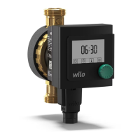
5.4 Accessories
Accessories must be ordered separately (see cat-
alogue):
• Switchgear for 1 or 2 pump operation
• External monitoring devices / tripping unit
• Level control (e.g. flow switch)
• Accessories for transportable wet sump installa-
tion (e.g. hose couplings, hoses, etc.).
• Accessories for stationary wet sump installation
(e.g. check valves, non-return valves, etc.)
6 Description and function
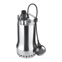
6.1 Description of the product (Fig. 1)
The pump can be completely submerged in the
fluid.
The submersible pump housing consists of stain-
less steel.
The electric motor is protected against the pump
chamber by a rotary shaft seal to seal the motor
against the oil chamber and a mechanical seal to
seal the oil chamber against the fluid. The
mechanical seal chamber is filled with medical
white oil so that the mechanical seal is lubricated
and cooled during a dry run. A further rotary shaft
seal protects the mechanical seal facing the fluid.
The motor is cooled by the surrounding fluid.
The pump is installed on the floor of a shaft. For a
stationary installation, it is bolted to a fixed pres-
sure pipe or for a transportable installation, it is
connected to a hose connection.
The pumps are commissioned by plugging in the
protective contact plug.
They operate automatically, when the float switch
switches the pump on from a certain water level
“h” (Fig. 2) and switches it off at a minimum water
level “h1”.
The motors are equipped with thermal motor pro-
tection, which switches off the motor automati-
cally if it overheats and switches it on again when
it has cooled down. The condenser is integrated in
the single-phase motor.
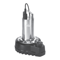
Version TSW with turbulator
For waste water with precipitating and floating
particles, the submersible pump has been
equipped with a turbulator at the suction strainer.
Precipitating particles are continuously whirled up
in the suction area of the pump and pumped off
with the water. Therefore, mud accumulation in
the pump shaft, with problematic consequences
such as clogging of the pump and odour forma-
tion, is largely prevented.
If the removal of the waste water does not allow
any interruption, a second pump (automatic
standby pump), together with the necessary
switchgear (accessory), increases the operating
reliability if the 1st pump develops a fault.
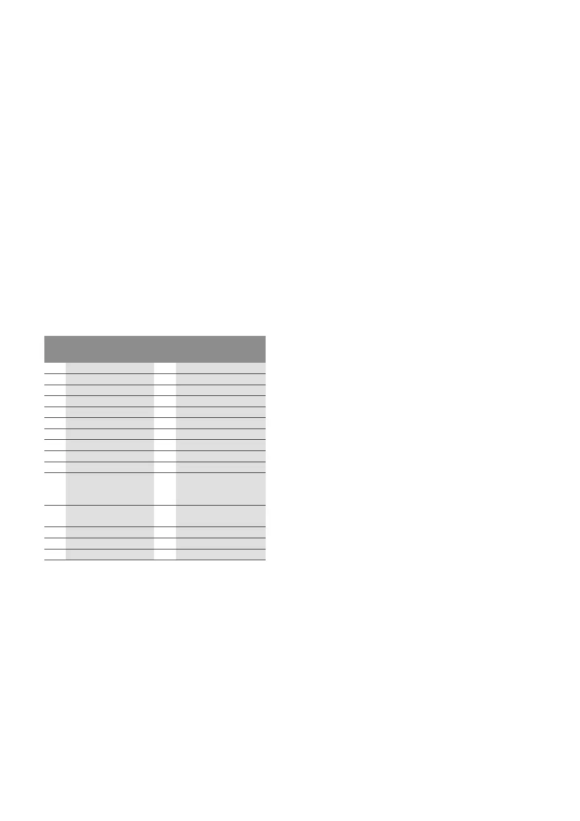
Pos. Description of the
component
Pos. Description of the
component
1 Cable and float switch 16 Rotary shaft seal
2 Clip for float switch 17 O-ring
3
Cap nut 18 Supporting ring
4
Housing 19 Screw
5 Motor cover, top 20 Pump housing
6
Screw 21 Impeller
7
Motor housing 22 Washer
8 Rotary shaft seal 23 Cap nut
9
Circlip 24 Strainer
10 Washer 25 Screw
11
Mechanical seal 26 Hose connector
Ø 32 mm / R 1
(not illustrated)
12 Seal 27 Non-return valve
(not illustrated)
13 O-ring 28 Guide plate
14
Seal housing 29 Turbulator
15
Screw