Installation and operating instructions Wilo-Yonos ECO BMS 27
English
6.2 Function of the pump
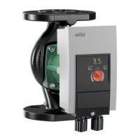
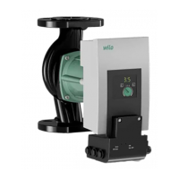
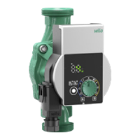
There is a control module (Fig. 1, item 5) in axial design on the motor housing, which con-
trols the differential pressure of the pump to a setpoint within the control range. Depend-
ing on the control mode, the differential pressure follows different criteria. In all control
modes, however, the pump adapts itself continuously to the changing power require-
ments of the unit, which is the case especially when thermostatic valves, zone valves or
mixers are used.
The basic advantages of the electronic control are:
• Energy savings and hence reduction of the operating costs,
• Reduction of flow noises,
• Reduction of the number of differential pressure valves required.
6.2.1 Settings
On the front of the control module is the “red button” (Fig. 1, item 4) as a central operating
element, which features three setting ranges.
The following settings can be made:
Variable differential pressure setting range (Dp-v):
Fig. 1, item 3: The control mode Dp-v is active
Constant differential pressure setting range (Dp-c):
Fig. 1, item 2: The control mode Dp-c is active
Setting range Ext. In:
Fig. 1, item 1: External speed adjustment by 0–10V analogue input.
6.2.2 Differential pressure control modes
Variable differential pressure (Dp-v):
The electronics change the differential pressure setpoint to be maintained by the pump
in linear form between ½Hs and Hs. The differential pressure setpoint Hs falls or increases
with the flow rate (Fig. 5), factory setting.
Constant differential pressure (Dp-c):
The electronics maintain the differential pressure created by the pump above the permit-
ted flow range constantly at the selected differential pressure setpoint Hs up to the max-
imum pump curve (Fig. 6).
6.2.3 Control signal 0–10V
The function linked to the 0-10V analogue control signal behaves as follows (Fig. 7):
U < 1 V: Pump stops
2 V < U < 3 V: Pump runs at minimum speed (starting)
1 V < U < 3 V: Pump runs at minimum speed (operation)
3 V < U <10 V: Speed varies between n
min
and n
max
(linear)
6.2.4 General functions of the pump
• The pump is equipped with an electronic overload protection function which switches off
the pump in the event of an overload.
 Loading...