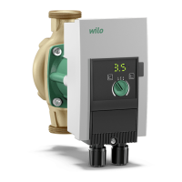
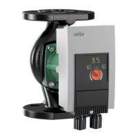
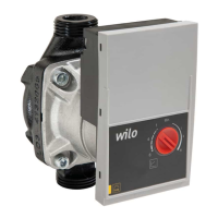
Installation and operating instructions Wilo-Yonos ECO BMS 33
English
8.2 Selecting the control mode
8.3 Adjusting the pump output
During planning, the unit is designed for a specific duty point (hydraulic full-load point for
maximum heating power requirement calculated). During commissioning, the pump out-
put (delivery head) is set according to the duty point of the system. The factory setting
does not correspond to the output required for the system. It is determined with the help
of the pump curve diagram for the selected pump type (from catalogue/data sheet). See
also Figs. 5 and 6.
Control modes Dp-c and Dp-v:
System type System conditions Recommended
control mode
Heating/ventilation/air-condi-
tioning systems with resistance
in the transfer section (room
radiator + thermostatic valve)
£ 25% of the total resistance
1. Two-pipe system with thermostatic/zone
valves and virtually no user authority
•H
N
> 4 m
• Very long distribution lines
• Strongly throttled line stop valves
• Sectional differential pressure control
• High pressure loss in system parts through
which total volume flows (boiler/refriger-
ating machine, any heat exchanger, distri-
bution line up to 1st branch)
2. Primary circuits with high pressure loss
Dp-v
Heating/ventilation/air-condi-
tioning systems with resistance
in the generator/distribution
circuit £ 25% of the resistance
in the transfer section (room
radiator + thermostatic valve)
1. Two-pipe system with thermostatic/zone
valves and high user authority
•H
N
£
2 m
• Converted gravity heating systems
• Conversion to large temperature spread
(e.g. district heating)
• Low pressure loss in system parts, through
which total volume flows (boiler/refriger-
ating machine, any heat exchanger, distri-
bution line up to 1st branch)
2. Primary circuits with minor pressure loss
3. Underfloor heating systems with thermo-
static or zone valves
4. One-pipe systems with thermostatic valves
or line stop valves
Dp-c
Dp-c (Fig. 6) Dp-v (Fig. 5)
Duty point on max-
imum pump curve
Starting at the duty point, draw towards the left. Read off setpoint H
S
and set
the pump to this value.
Duty point within
the control range
Starting at the duty point, draw
towards the left. Read off setpoint H
S
and set the pump to this value.
Move to max. pump curve along con-
trol curve, then horizontally to the
left, read off setpoint H
S
and set the
pump to this value.
Setting range H
min
, H
max
, see 5.1 Type key
 Loading...

