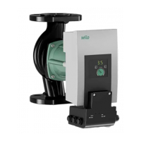
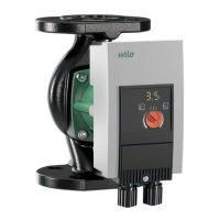
Installation and operating instructions Wilo-Yonos MAXO/-D 15
English
Factory setting
The pumps are delivered in control mode Δp-v. Here, the delivery head setpoint is preset
to between ½ and ¾ of the max. delivery head setpoint, depending on the pump type (see
pump data in the catalogue). The required pump output is to be adjusted, depending on
the system requirements.
NOTE: In the event of a power interruption, the delivery head setpoint is retained.
8.2.2 Control mode selection
System type System conditions Recommended
control mode
Heating/ventilation/air-condi-
tioning systems with resistance
in the transfer section (room
radiator + thermostatic valve)
25% of the total resistance
1. Two-pipe systems with thermostatic/
zone valves and low valve authority
•H
N
> 4 m
• Very long distribution lines
• Strongly throttled shut-off valves for pipe
sections
• Sectional differential pressure control
• High pressure losses in the system parts
through which the entire volume flows
(boiler/refrigerating machine, heat
exchanger possibly, distribution pipeline
up to the first branch)
2. Primary circuits with high pressure losses
p-v
Heating/ventilation/air-condi-
tioning systems with resistance
in the generator/distribution
circuit 25% of the resistance
in the transfer section (room
radiator + thermostatic valve)
1. Two-pipe systems with thermostatic/
zone valves and high valve authority
•H
N
2 m
• Converted gravity heating systems
• Conversion to large temperature spread
(e.g. district heating)
• High pressure losses in the system parts
through which the entire volume flows
(boiler/refrigerating machine, heat
exchanger possibly, distribution pipeline
up to the first branch)
2. Primary circuits with low pressure losses
3. Floor heating systems with thermostatic
or zone valves
4. One-pipe systems with thermostatic or
line shutoff valves
p-c
Heating/ventilation/air-condi-
tioning systems
Constant volume flow
Manual setback operation via speed stage set-
ting
n = const.