A l e x i A O w n e r ’ s M A n u A l
32
Wilson Audio Specialties
tion delay adjustment. The spike also provides proper coupling of the Upper Array to
the Woofer Module. Shorter “AA” spikes are always installed in the front two positions
(the threaded holes located near the bottom front of the enclosure). The spike-type is
stamped in the round top of the spike. The two “AA” spikes screw into the Upper Array
as shown in Figure 4. The spikes should be screwed in all the way, until they are hand
tight. Do not over tighten spikes.
Section 3.2—Alexia Propagation Delay Adjustment
Room Setup
As indicated in Figure
6, the Alexia system al-
lows for different listening
distances (away from the
speakers) and listening ear
heights (measured distanc-
es from the floor to your
ear). For each distance/ear
height combination there is
a unique alignment geom-
etry.
To make correct in-
home set up of the Alexia
possible without test
equipment, Wilson Audio
has measured the correct
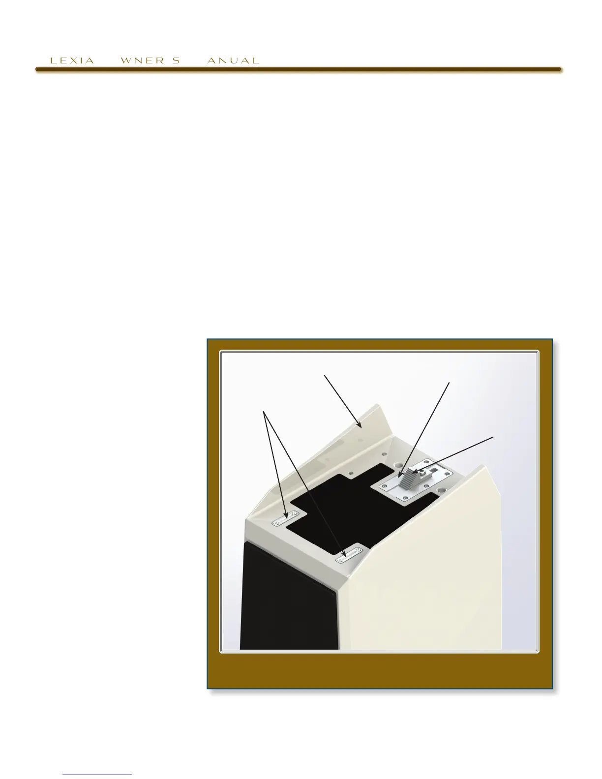
figure 5—tOp Of the wOOfer MOdule, with spike guides And
reAr spike receptAcle�
Upper ArrAy Spike
plAcement GUide
rotAtion lAdder
pAinted inner edGe And
top of Woofer modUle
forWArd/BAck
nUmBered trAck