2
1 Safety information ........................................................................................................................................................ 3
1.1 Safety ................................................................................................................................................................ 3
1.2 230V AC ............................................................................................................................................................ 3
1.3 Back-up batteries .............................................................................................................................................. 3
1.4 Application ......................................................................................................................................................... 3
1.5 Cable routing and electrical connection ............................................................................................................. 3
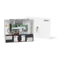
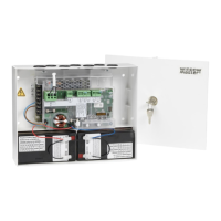
2 Structure of the smoke panel ...................................................................................................................................... 4
2.1 ISO 21927-9 related data .................................................................................................................................. 4
2.1.1 Access levels................................................................................................................................................. 5
3
Max numbers of actuators per motor line and panel
.................................................................................................... 5
4 Accessories and spare parts ...................................................................................................................................... 6
5 Technical data .............................................................................................................................................................. 7
6 Mounting ....................................................................................................................................................................... 8
7 Installation .................................................................................................................................................................... 8
7.1 Cable routing ..................................................................................................................................................... 8
7.2 Cables into housing ........................................................................................................................................... 9
7.3 Connection of safety earth wire and 230V AC ................................................................................................... 9
7.4 Installation of the break glass unit, ventilation keypad and smoke detector ...................................................... 9
7.5 Assembly instructions ........................................................................................................................................ 9
8 Cable dimensioning ..................................................................................................................................................... 9
8.1 Maintaining the cable functions ......................................................................................................................... 9
8.2 Max. cable Length ............................................................................................................................................. 9
8.2.1 Formula for the calculation of the maximum actuator cable length ............................................................. 10
8.2.2 Max cable length – ±24V standard actuators .............................................................................................. 10
8.2.3 Max cable length – actuators with MotorLink
®
............................................................................................. 10
9 Cable plan for connection to WSC 104 .................................................................................................................... 12
10 Description of card and mains connection .............................................................................................................. 12
10.1 Mains connection and power supply (WCA 1P1) .............................................................................................12
10.2 Main card WSA 1SS .........................................................................................................................................13
11 DIP switch configuration ........................................................................................................................................... 18
12 Back-up batteries ....................................................................................................................................................... 18
13 Configuration of panel ............................................................................................................................................... 19
13.1.1 Motor line .................................................................................................................................................... 19
13.1.2 Smoke zone ................................................................................................................................................ 19
13.1.3 Local input ................................................................................................................................................... 19
13.1.4 Local output ................................................................................................................................................. 19
14 Fault detection via LED.............................................................................................................................................. 19
14.1 Fault detection on the smoke panel..................................................................................................................19
14.2 Fault indication on break glass unit ..................................................................................................................21
15 Hardware error ........................................................................................................................................................... 21
15.1 Error on the Power supply ................................................................................................................................21
15.1.1 Blown fuses – 6.3A slow ............................................................................................................................. 21
16 Commissioning and test run ..................................................................................................................................... 21
16.1 The control ventilation panel is completely installed, without the operating voltage applied .............................21
16.2 With mains voltage, without accumulator .........................................................................................................21
16.3 With mains voltage, with accumulator ..............................................................................................................21
16.4 Ventilation keypad ............................................................................................................................................22
16.5 Break glass unit WSK 50x ................................................................................................................................22
16.6 Smoke detectors ..............................................................................................................................................22
16.7 Emergency power supply test ..........................................................................................................................22
16.8 Wind/rain detector ............................................................................................................................................22
17 Maintenance ............................................................................................................................................................... 22
17.1 Maintenance agreements .................................................................................................................................23
17.2 Replacement 1SS card ....................................................................................................................................23
18 Declaration of Conformity and Declaration of Performance .................................................................................. 23
Appendix A - WSC 104 S 0101 – DIP Switch setting log............................................................................................... 24