Up to 5 break glass units type WSK 50x can be connected to the panel, but only
1 WSK 501 / 502 per panel.
Smoke detectors and ventilation keypads can only be connected to the break
glass units type WSK 501 / 502. Smoke detectors and ventilation keypads cannot
be connected to WSK 503 / 504.
Up to 10 smoke detectors can be connected to the system. Smoke detectors can
either be connected to the WSK 501 / 502 and/or the smoke detector input on the
main card.
There is no limit on the number of ventilation keypads connected to the WSK 501
/ 502.
1 x 4A motor line for ±24V standard or MotorLink
®
actuators
Plastic housing for surface mounting
224 x 283 x 85mm (H x W x D)
1.2kg no batteries, 4kg with batteries (2 x WSA 003)
Approved and certified according to EN 12101-10 and ISO 21927-9
CompactSmoke™ smoke ventilation panel, 2 x 10kΩ resistors, 1 x WSA 514 end
of line module. Back-up batteries included.
We reserve the right to make technical changes
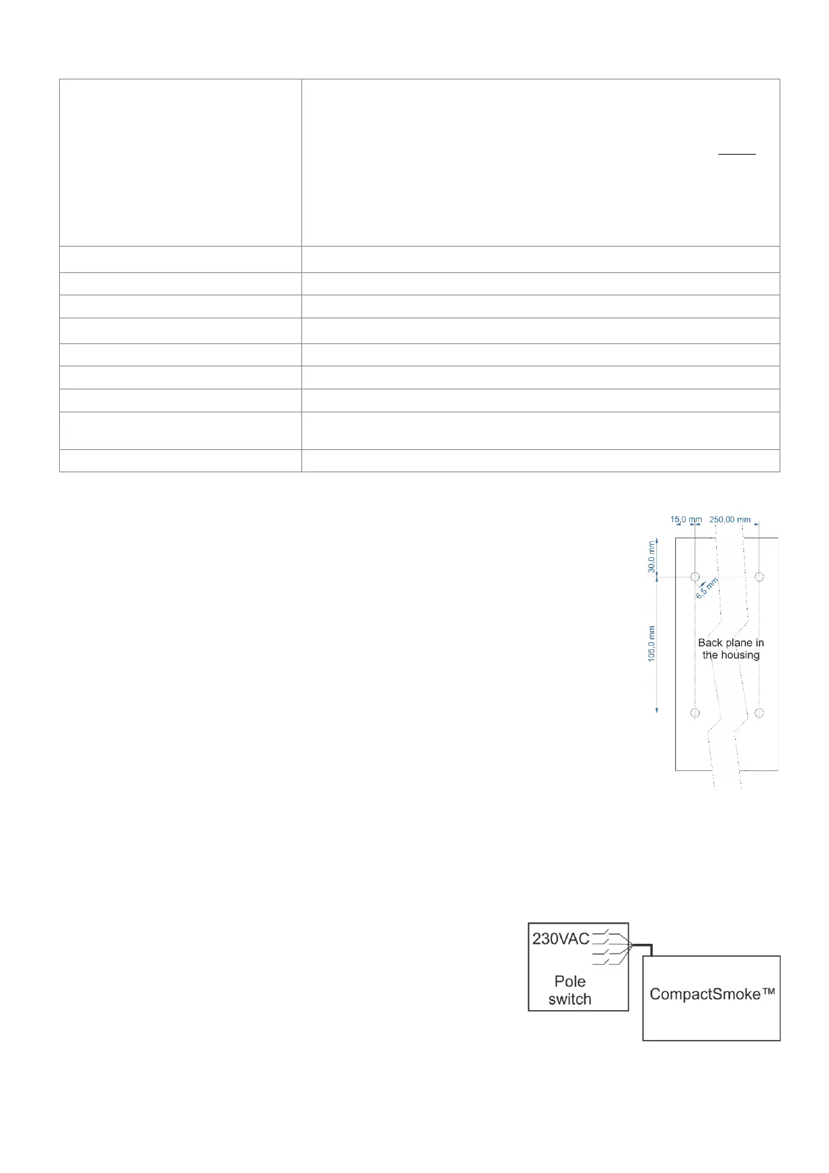
The smoke ventilation panel is fixed to the wall through the Ø6.5mm holes in the back plane of the
housing.
The smoke ventilation panel is to be located in a safe place, protected from the effects of fire and
smoke.
7 Installation
7.1 Cable routing
For cable routing we recommend the use of fire protected cables retaining their function E90 or E30.
See also chapter 8 “Cable dimensioning” in this instruction.
However, this has to be agreed with the Engineer or, if necessary, with the local fire protection department.
Do not reduce the cable cross sections specified in the cable lengths table.
All cables of the control (except the mains supply cable) carry 24V DC and
have to be routed separate from the mains supply cable. Adhere to the
pertinent national and local regulations when routing the cables.
Lead the connection cables into the housing of the control panel from above
and the cable glans shall comply with fire class V-1 (IEC/EN 60695-11-20 / UL
94) or higher and be in accordance with national and local regulations.
Ensure that the mains cable can be switched via an external or customer-supplied
two-pole switch element or a switch element controlling all poles – see drawing.