19
13 Configuration of panel
The smoke panel is configured by pressing the two keys ”↑” and ”↓” on the main card, at the same time for 5-10 seconds.
The smoke panel must be configured
- After re-installation, changes, or change of actuators
- When / if MotorLink
®
actuators are connected
- If the cables have been moved
- When components are removed from the panel
- If there has been a fault on the WSK-Link™. Error blink sequence 6, see section 14.1.
- When DIP switch 8 is changed from ON to OFF
Note, during reconfiguration the actuator output can be activated in both directions.
If the yellow diode on the main card blinks after a configuration, an error has occurred in the configuration, see section 14 “Fault
detection via LED” for identification of errors.
13.1.1 Motor line
Actuators are to be connected on the motor line. ±24V standard actuators or actuators with MotorLink
®
can be connected to the
motor line, the motor line can only be connected to one type of actuators – either ±24V standard or MotorLink
®
actuators. The
panel will automatically detect the type of actuator, which is connected to the panel.
13.1.2 Smoke zone
Depending on the settings on the DIP-switches the actuators will either open or close when the smoke panel is triggered, see
section 11.
13.1.3 Local input
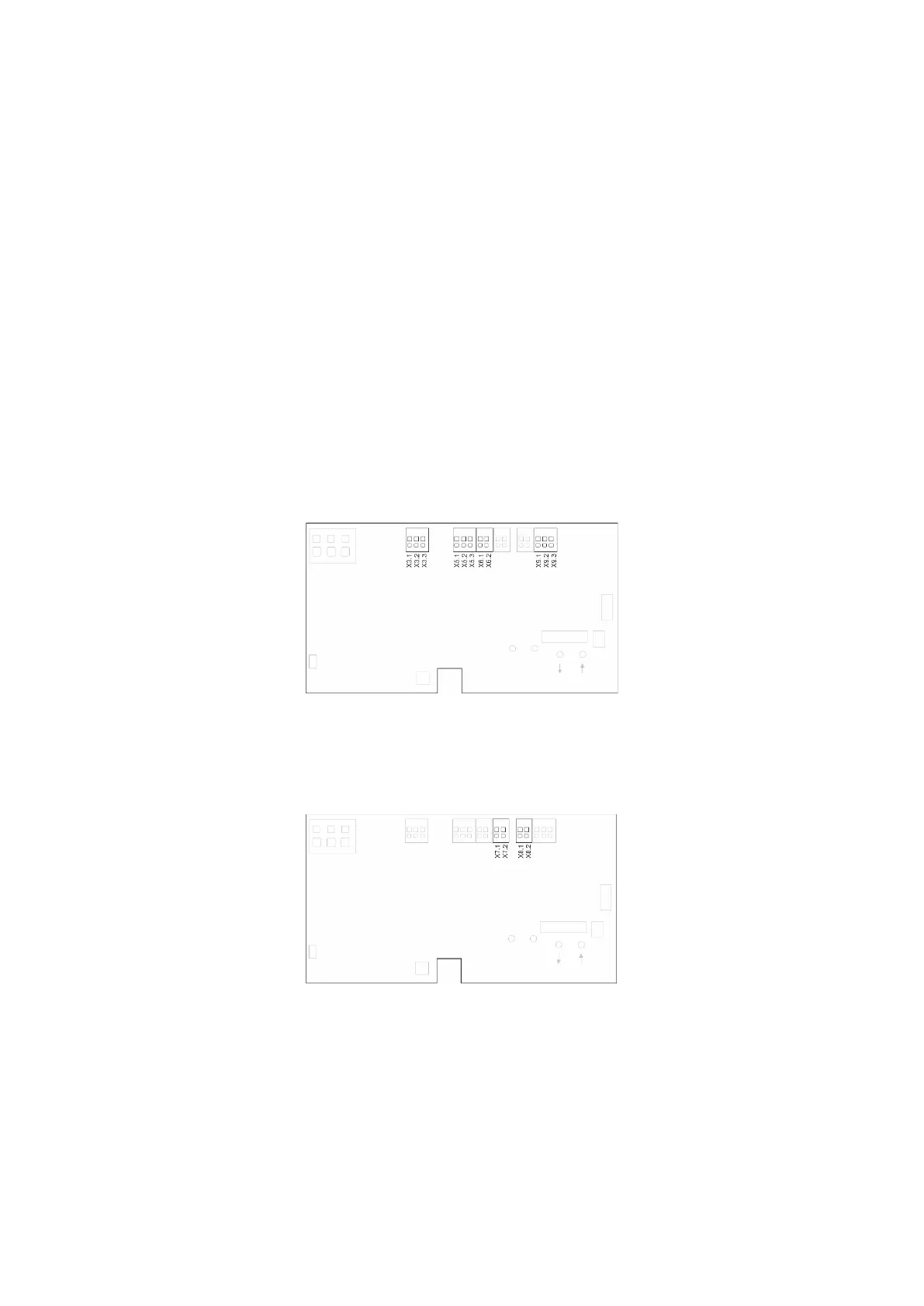
The four inputs on the panel are pre-configured with the functions as shown below.
X3 Comfort keypads
X5 Break glass unit
X6 Smoke detector
X9 Rain sensor
13.1.4 Local output
The output on the panel is pre-configured with the function as shown below.
X7 Alarm signal
X8 Fault signal to fire alarm system
14 Fault detection via LED
14.1 Fault detection on the smoke panel
In case of error on the panel, the yellow diode on the main card will blink and via blink sequence indicate an error message.
Depending on the type of error, the message will consist of 2 or 3 blink sequences, separated by a seconds pause. The first blink in
an error message has a duration of one second, and thereby indicating when the error message (1
st
blink sequence) begins. The
remaining blinks of the error message has a duration of 0.5 seconds. The error message is repeated until the error has been
rectified. Between 2 error messages there is a pause of 2 sec.