Do you have a question about the Winegard SK-SWM3 and is the answer not in the manual?
Disconnect coax and sheath cables from vertical ports before turret removal.
Remove the 9 screws holding the turret to the transition plate.
Disconnect cable connections from electronics module.
Use nut driver to remove the 4 screws holding the electronics module.
Remove the 4 screws holding the elevation motor in place.
Remove 2 screws securing wrap cable to turret, and remove wrap cable.
Install new wrap cable and secure using the 2 screws.
Place turret back on transition plate and secure using the 9 screws.
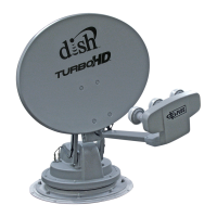
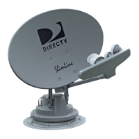
This document is an instruction manual for replacing the wrap cable on a Winegard Trav'ler Automatic Multi-Satellite TV Antenna, specifically for models SK-SWM3 and SK-1000. The manual provides step-by-step instructions for disassembling parts of the antenna, replacing the cable, and then reassembling the components.
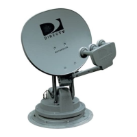
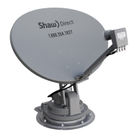
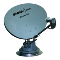
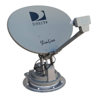
The Winegard Trav'ler Automatic Multi-Satellite TV Antenna is designed to provide satellite television reception for mobile applications, such as RVs. Its primary function is to automatically locate and lock onto available satellites, ensuring a consistent and reliable TV signal for users on the go. The "Automatic Multi-Satellite" aspect indicates its ability to acquire signals from multiple satellites, likely supporting various satellite TV providers and channels. The antenna is typically mounted on the roof of a vehicle and can be stowed when not in use or during travel.
The wrap cable, which is the focus of this replacement manual, is a critical internal component of the antenna system. It is responsible for carrying power and data signals between different parts of the antenna, particularly those that move during the antenna's aiming and stowing operations. Given its role in a moving mechanism, the wrap cable is designed to withstand repeated flexing and movement. Over time, however, such cables can wear out or become damaged, necessitating replacement to maintain the antenna's functionality.
The Trav'ler antenna is characterized by its automatic operation, which simplifies the user experience. Instead of manually aiming the dish, users can rely on the system to automatically find and lock onto the desired satellites. This is a significant convenience for RV owners who frequently change locations. The multi-satellite capability means that the antenna can access a wider range of programming, potentially supporting different satellite TV services or providing access to more channels from various orbital positions.
The antenna is designed to be robust for outdoor use, capable of withstanding various weather conditions. Its stowed position feature is crucial for travel, protecting the dish from wind resistance and potential damage while the vehicle is in motion. The interface box, mentioned in the instructions, is the control unit that allows users to operate the antenna and provides power to the system.
The manual details a specific maintenance procedure: replacing the wrap cable. This indicates that the antenna is designed with a degree of serviceability, allowing for component replacement rather than requiring a full unit replacement in case of cable failure. The process involves several key steps:
Removing the Turret: This initial phase involves disconnecting external cables (coax and sheath cables) and removing the cable cover. The power coupler and retaining nut for the power/control cable are unthreaded and removed. Coax ports are detached from the base and top of the turret, and then the nine screws holding the turret to the transition plate are removed. This suggests a modular design where the main rotating part of the antenna (the turret) can be separated for internal access.
Accessing Internal Components: After removing the turret, the gasket and moisture barrier are removed, highlighting the importance of these components in protecting the internal electronics from environmental elements. A p-Clip holding the wrap cable in place is also removed, indicating a secure routing mechanism for the cable.
Removing Electronics: The electronics module is disconnected from its cables and then unscrewed and removed. This step shows that the electronic control unit is also a separate, replaceable module, further emphasizing the antenna's serviceability. The wrap cable is then removed from a rubber grommet on the electronics module, suggesting a sealed entry point to protect the electronics.
Removing Elevation Motor Assembly: The elevation motor, responsible for adjusting the dish's vertical angle, is unscrewed and its cable disconnected. This indicates that the motor is also a distinct, replaceable unit.
Replacing the Wrap Cable: The old wrap cable is removed by unscrewing it from the turret. The new wrap cable is then installed and secured with screws. This is the core maintenance step, demonstrating that the cable is a specific, identifiable part that can be swapped out.
Reinstalling Components: The reinstallation process essentially reverses the disassembly steps. The elevation motor is reconnected and secured. The wrap cable is fed through the rubber grommet on the electronics module, and the electronics module is resecured and its cables reattached in a specific order (12-pin connector, 8-pin connector, male coax on wrap cable, male coax on included mini cable). This ordered reattachment is crucial for proper functionality.
Securing Wrap Cable and Reinstalling Turret: The coax ports are re-seated in a specific order (Black/Red, Blue/Blue, Blue/Black for the top; Blue/Black, Blue/Blue, Blue/Red for the base) and secured with nuts. The p-clip is re-secured to the turret. The gasket and moisture barrier are realigned, and the turret is placed back on the transition plate and secured with the nine screws.
Final Connections: The data cable connection is slid through a hole in the base and secured with the retaining nut. The cable cover is reinstalled with four screws. Finally, the coax cables at the base and the sheath cable are reconnected to the vertical ports in a specified order.
The detailed nature of these instructions, including specific screw counts, cable orders, and the use of a provided nut driver, suggests that Winegard has designed the Trav'ler antenna with a clear pathway for component-level maintenance. This approach can extend the lifespan of the antenna by allowing for the replacement of wear-prone parts like the wrap cable, rather than requiring the purchase of an entirely new unit. The emphasis on proper alignment of gaskets and moisture barriers also highlights the importance of maintaining the antenna's weatherproofing during maintenance.
| Type | Satellite Antenna |
|---|---|
| Connector Type | F-Type |
| Compatibility | DIRECTV SWM |
| Power Supply | Power inserter required (not included) |
| Mounting | Roof Mount |