60708-162
4094-00
10
*************
***** WARNING *****
*************
PERSONAL DANGER - These unit are shipped with a
NEUTRAL TO GROUND BOND INSTALLED. If your system
already has a neutral to ground bond then you must run a
separate ground lead to that location AND UNBOND THE
JUMPER IN THE CONNECTION PANEL. For additional
questions refer to the current National Electric Code on
grounding.
*************
***** WARNING *****
*************
EQUIPMENT DAMAGE - When installing a Three Phase 240
volt system be sure you know which lead is the high voltage
“wild” leg (208 Volt line to neutral). The generator normally
carries the high voltage on the G2 lead.
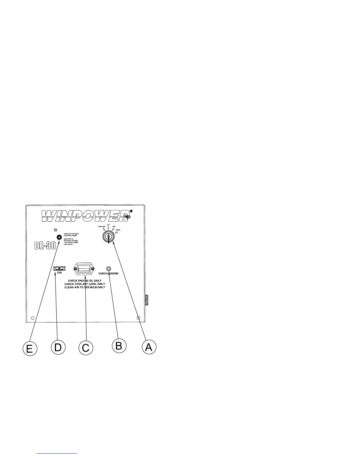
ENGINE CONTROL PANEL
LAYOUT MANUAL KEY START
A. FOUR POSITION START SWITCH
1. Preheat - This position is used on the DE20 and DE30
only. With the switch in this position the glow plugs on the
engine are activated.
2. OFF - In this position all power to the engine is
turn off and the engine is stopped.
3. RUN - With the switch in this position the fuel solenoid
and the fuel pump on the engine are activated. A 12 Volt
signal is also being sent to the voltage regulator on the
engine alternator to activate it.
4. START - This position on the switch will activate the
starter on the engine to start it.
B. CHECK ENGINE LIGHT - This light will come on when the
low oil pressure switch or the high water temperature sensor
switches have been activated on the engine. This light will also
come on when you go to start the engine, and stay on until the
engine has built sufcient oil pressure to open the low oil pressure
switch.
C. RUNNING TIME METER - This meter records the actual
hours of engine operation.
D. 25 AMP FUSE - This fuse protect all the DC wiring in the
engine control panel and on the engine. If this fuse if blown
nothing will work on the engine.
E. SAFETY LATCHING RELAY - This safety latching relay
provides the 12 volt DC power to the fuel solenoid and the engine
alternator eld circuit during normal operation. If the system
experiences a low oil pressure fault or a high water temperature
fault this relay will trip disconnecting the fuel solenoid and shutting
down the engine. When tripped the button on the panel will
extend out about 1 inch. This button must also be held in during
starting until the check engine light goes out.
INITIAL START UP
MANUAL KEY START
*************
***** WARNING *****
*************
EQUIPMENT DAMAGE - DO NOT jump start these engine
generator sets. Starting these units on a low battery or jump
starting them may cause damage to the engine controls.
Use the following check list to verify correct installation before
starting the engine:
1. Engine oil. Fill as required with proper grade/qty.
2. Engine coolant. Fill as required with proper mixture.
3. Unit mounting base properly bolted down.
4. Clearance for service and maintenance on all sides.
5. Proper fuel line material and size.
6. All fuel line connections tight.
7. Battery connections clean and tight.
8. Battery fully charged.
9. All AC and DC wiring installed and properly protected.
After completing the above checklist, the engine-generator set is
ready for the initial start-up test.
STARTING PROCEDURE
1. Rotate start switch (A) to the preheat position and hold for 10
seconds. NOTE: This step applies to the DE20 & DE30 ONLY.
2. Rotate the Start Switch (A) to the Run position. Then while
depressing the Safety Latching Relay button (E) rotate the switch
to the Start position. At this point the starter should engage and
the unit will start.
 Loading...