MRK16 16 channels ultra-wideband rack unit
10
OPTION - EXPANSION BOARD 3 (EX3)
Standard conguration example
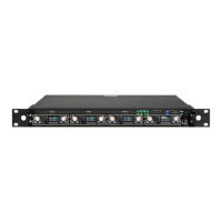
The Expansion Board 3 (EX3) is a slot-in accessory designed to convert two optical input
signals into RF. This setup enables users to deploy receiving antennas at a much greater
distance (see diagram). Since the EX3 operates independently, to feed the RF signals into the
MRK16, you need to daisy chain the RF outputs from the EX3’s BNC connectors into the main
BNC inputs of the MRK16.
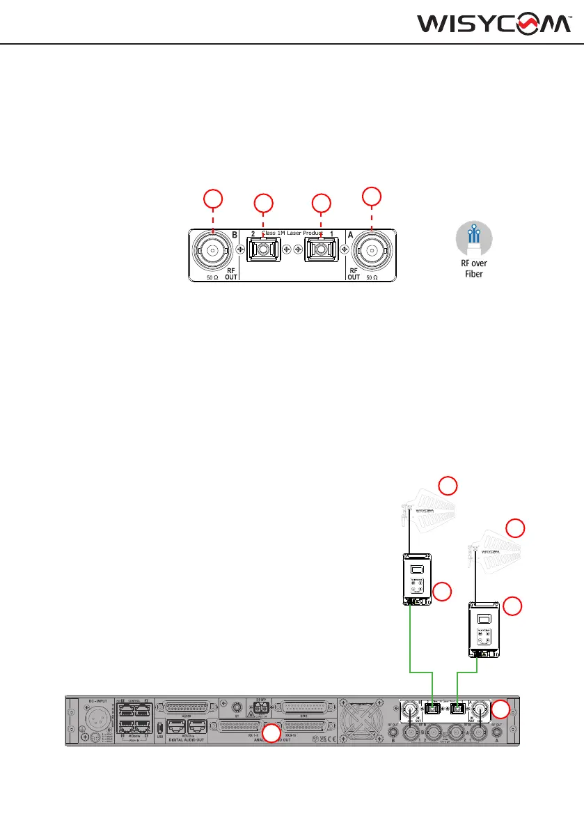
In this setup example, we are using the EXP3 (2) module
mounted on the MRK16 (1) rear panel to receive signals from
two LBN2 antennas (5, 6), which are positioned in a remote
location hundreds of meters/feet away from the control room
where the MRK16 is located. The signal from the antennas is
converted to optical signals by two BFLT modules (3, 4) located
near the antennas. These optical signals are then transmitted
back to the EXP3 module over two single-mode optical bers.
Note: The primary limitation in this setup is the loss of the ber
cable, which is approximately 0.4 dB per kilometer for a 4 mW
laser used by the BFLT modules. Every 3 dB of loss equates
to a 50% decrease in optical power. Therefore, the maximum
distance that can be reliably covered depends on the total ber
loss encountered, with approximately 7 km reducing the optical
power by 50%.
21G BFLx1 QUICK MANUAL
RF OUT
9 ~ 18 Vdc
BT
RX
OPT
IN
RX
LASER 1M
RF INBT
TX
OPT
9 ~ 18 Vdc
OUT
TX
21G BFLx1 QUICK MANUAL
RF OUT
9 ~ 18 Vdc
BT
RX
OPT
IN
RX
LASER 1M
RF INBT
TX
OPT
9 ~ 18 Vdc
OUT
TX
1. BNC output B
2. RF over Fiber Input 2 - SC/APC standard
3. RF over Fiber Input 1 - SC/APC standard
4. BNC output A
1
2
1
4
3
5
6
2 3
4