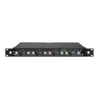
MRK16 16 channels ultra-wideband rack unit
9
Tip: When an antenna shows as overloaded, you can reduce the RF input to the antenna
using the antenna gain control. Alternatively, try moving further away from the source of the
interfering RF signal to mitigate the overload issue.
RF SETUP
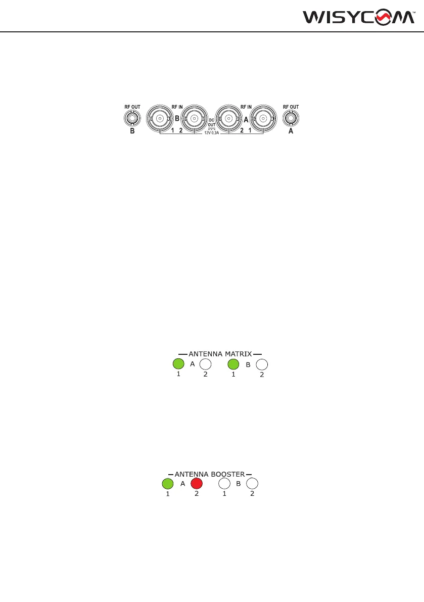
The MRK16 features 2 diversity RF inputs divided into A1, B1 and A2, B2. These four connec-
tors are BNC type. Each connector is capable of providing 12V bias
The MRK16 has 2 diversity outputs which uses the SMA connector RF OUT A and RF OUT
B. Thanks to these connectors it’s possible to cascade multiple MRK16 (up to 8 units without
any noise increase) or any other wireless microphones system.
Zone 1 & 2 menu
From the setup menu, it is possible to congure the RF zones: Zone 1 (A1, B1) and Zone 2
(A2, B2).
Status:
This setting determines whether the RF inputs are ON or OFF. When set to ON, RF signals
are allowed to pass through. When set to OFF, the input is disabled, blocking any incoming
signals to protect the unit from unwanted interference.
The status of the antennas can be monitored from the front panel LED on the unit or via the
Wisycom Manager:
- A green LED indicates that the zone is enabled, allowing reception from those antennas.
- If the LED is off, the zone is disabled, and reception from that zone will not occur
RF
This setting provides the possibility of switching ON and OFF one or both inputs of your
zones.
BOOSTER
Switch this option on to provide 12V bias to the connected active antennas or boosters. You
can verify if the bias is enabled on that specc input connector by checking the LED on the
front panel. Red LED means antenna is overload, off that there is no bias and if green, that the
bias is enabled.
A
B
ON
1
3
2
4
PWR
EXIT
MENU
SEL
SYNC
SCAN
fn
BT
B
2
4
SYNC
SCAN
fn
T
A
B
ON
1
3
2
4
PWR
EXIT
MENU
SEL
SYNC
SCAN
fn
BT
B
2
4
SYNC
SCAN
fn
T
A
B
ON
1
3
2
4
PWR
EXIT
MENU
SEL
SYNC
SCAN
fn
BT
B
2
4
SYNC
SCAN
fn
T
A
B
ON
1
3
2
4
PWR
EXIT
MENU
SEL
SYNC
SCAN
fn
BT
B
2
4
SYNC
SCAN
fn
T
A
B
ON
1
3
2
4
PWR
EXIT
MENU
SEL
SYNC
SCAN
fn
BT
B
2
4
SYNC
SCAN
fn
T
A
B
ON
1
3
2
4
PWR
EXIT
MENU
SEL
SYNC
SCAN
fn
BT
B
2
4
SYNC
SCAN
fn
T
A
B
ON
1
3
2
4
PWR
EXIT
MENU
SEL
SYNC
SCAN
fn
BT
B
2
4
SYNC
SCAN
fn
T
A
B
ON
1
3
2
4
PWR
EXIT
MENU
SEL
SYNC
SCAN
fn
BT
B
2
4
SYNC
SCAN
fn
T