U
SB
M
OTION
C
A
RD
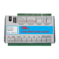
model :MK4- V
System :MACH 3
QC:01
2016-9-13
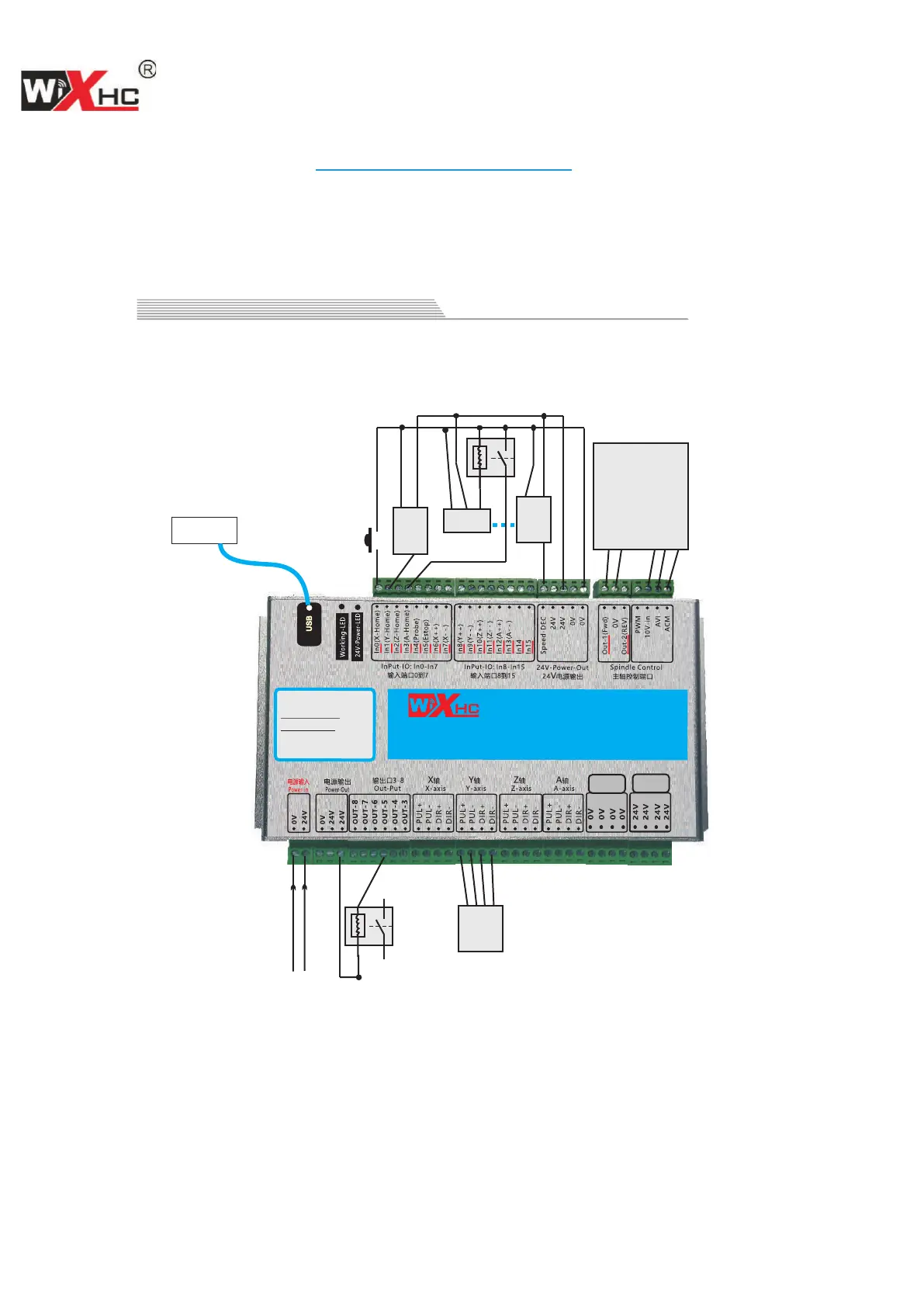
USB 4-axis Card
电源0V
电源24V
Wiring diagram shows
NOTE: If the inverter is turned on, the control card is not working properly because of interference caused
by the inverter; Replace inverter.
24V Power Input
Step or servo driver
Relay
Computer
NPN Photoelectric switch
OUT
GND
VCC
Mechanical switch
Inverter
Inverter forward signal
Digital signal ground
Inverter 10V output
0-10V analog voltage
Analog signal ground
Mechanical switch
Input IO Connect NPN (PNP) Photoelectric switchMechanical switch or
Input signal must be active low
OUT
GND
VCC
PNP Photoelectric switch
Relay
OUT
GND
VCC
hall switch
DIR-
PUL-
DIR+
PUL+
ChengDu XinHeCheng Technology Co.,Ltd
www.cdxhctech.com
<9>
 Loading...