Operating manual PMF/GMF Page 16 of 37 B0343
4. Description of function
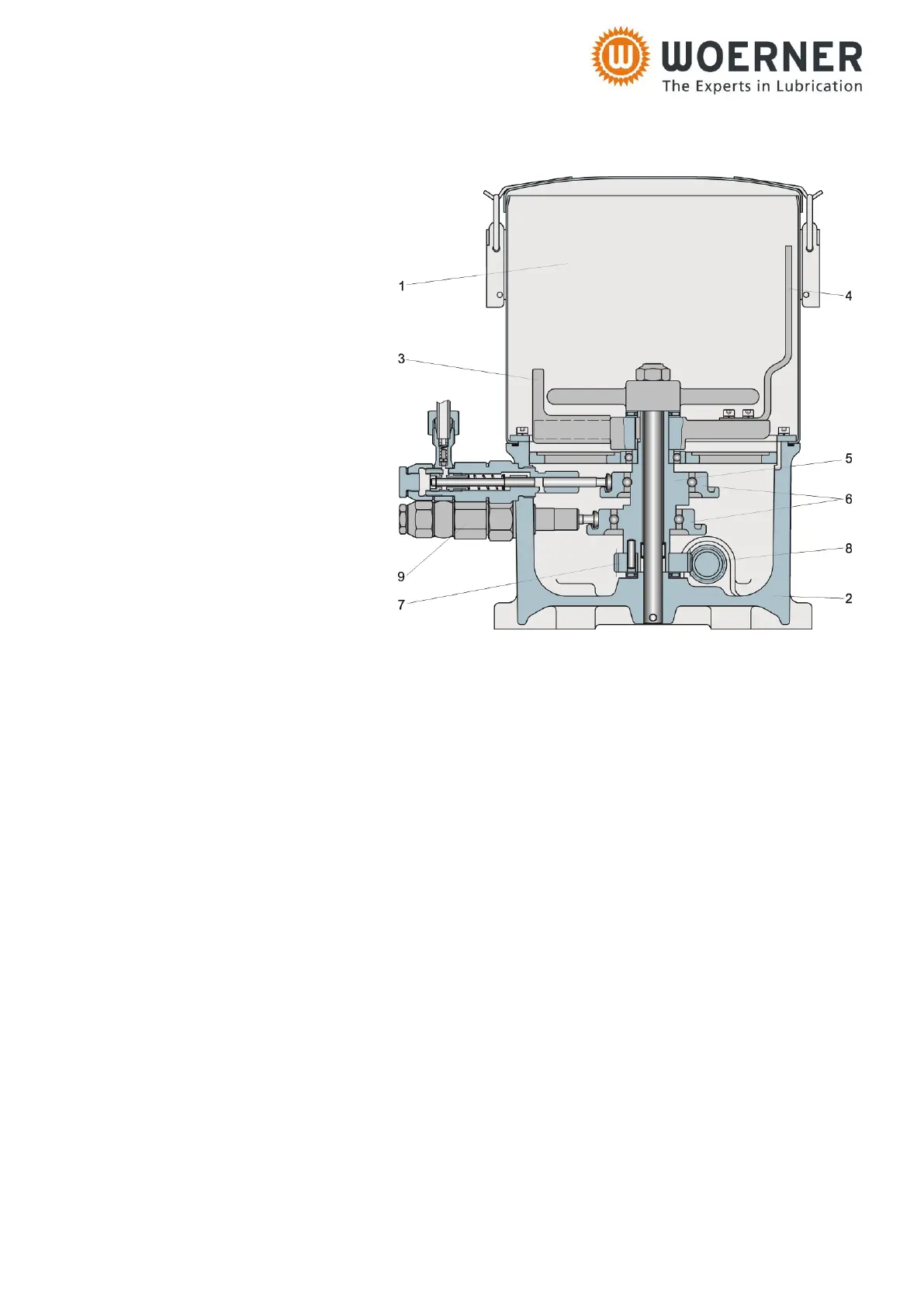
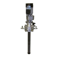
4.1 Components
1 Reservoir
2 Pump case
3 Agitator
4 Agitator blade
5 Pump shaft
6 Pressure ring
7 Worm wheel
8 Worm
9 Pump element
4.2 Drive
4.2.1 Motor
The pump unit is motor-driven through a right-angle gearbox flange-mounted on the side of
the pump case.
4.2.2 Hydraulic motor
The pump unit is driven by hydraulic motor and right-angle gearbox flange-mounted on the
side of the pump case.
4.2.3 Oscillating drive
An external eccentric transmits a longitudinal movement onto a rocker arm. In a gearbox, the
oscillation is converted into rotation to drive the worm shaft in the pump case.
4.3 Function
The drive puts the pump shaft into rotation through a worm gearing. Together with this pump
shaft, a pressure ring rotates eccentrically, which the pump elements are hung in. Due to the
eccentricity of the pressure ring related to the pump shaft, each displacing piston passes,
mechanically operated, through equally long pressure and suction strokes with every revolu-
tion of the pump shaft. The function of the pump elements will be explained later. An agitator
is linked with the pump shaft forcing the lubricant to the suction borehole of the pump ele-
ments to comminute air bubbles.