Operating manual PMF/GMF Page 32 of 37 B0343
8.3 Inspection chart
Inspect if the safety equipment has been installed
and works properly.
Inspect the lubricant lines and connections for
mechanical damage and leakage.
Inspect the pump unit and components for mecha-
nical damage and leakage.
Drive "O", filling quantity 15 cm³,
gear oil ISO VG 220.
Drives "L", "M", "N" und "V" from July 2013.
Check the filling level of the pump unit.
8.4 Repair
Replacing the pump element:
Note! Before dismantling the pump element, drain the reservoir, other-
wise lubricant may escape.
Note! When dismounting the pump element make sure that the dis-
placing piston is removed from the reservoir as well. If not, the
pump may be damaged and consequently, fail.
Cautiously screw out the pump element. Replace the pump element by a spare one.
Assemble the pump element as follows:
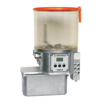
Insert the pump element, with the displacing
piston pulled out by its half, under an angle to
top into the supporting bore of the case.
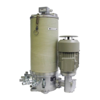
Tilt the pump element downward as soon as the
displacing piston head rests on the pressure ring
and engages into the slot of the pressure ring.
Screw in the pump element.
Fill the borehole of the pump element supporting the displacing pistons with grease to
facilitate both assembly and start-up.
For any further repair, please contact WOERNER.