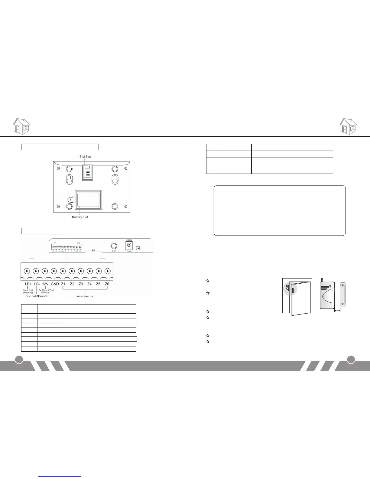
Alarm Panel back schematic diagram:
Wired terminal block:
Installation Installation
3
4
Note:
1.“LB-” and “LB+” are to connect external speaker. If you think
the internal speaker is not loud enough, please contact us for
professional speakers.
2.Connect one cable of the wired sensor to GND and the other
to “Z1/Z2/Z3…/Z6”.
3.Please pay attention to the siren connection. Do not mix the
two cables together when connecting. Otherwise, it will
damage the transistor in the main panel.
[Door sensor]
Door sensors are used for detecting the status of open and close of
windows and doors. It will detect it and send the signal to main panel.
Tear apart the double-side
adhesive tape on the magnet
and the transmitter. Then
adhere them to the appropriate
position.
Magnet should be near to the
side of transmitter with indicator.
The two should align with eachother and the distance should not
exceed 10mm.
Please plug out the antenna for better signal.
If the low-power indicator is on, please change the battery.
LB+ Positive of speaker (red cable)
2 LB- Negative of speaker (black cable)
3 12V 12V Output Port (Positive)
4 GND Ground
5 Zone 1 Wired sensor 1: support both NO and NC
6 Zone 2 Wired sensor 2: support both NO and NC
7 Zone 3 Wired sensor 3: support both NO and NC
8 Zone 4 Wired sensor 4: support both NO and NC
9 Zone 5 Wired sensor 5: support both NO and NC
10 Zone 6 Wired sensor 6: support both NO and NC
SIM Put SIM card in this card slot
2 Siren Plug in siren connector
3 Power Connect to the external power supply
4 Switch Switch for backup battery. Turn it on after
power on.
Less than 10mm
 Loading...