Heat Recovery unit CWL-300(B) / CWL-400(B) with option PCB 11
Settings Chapter 4
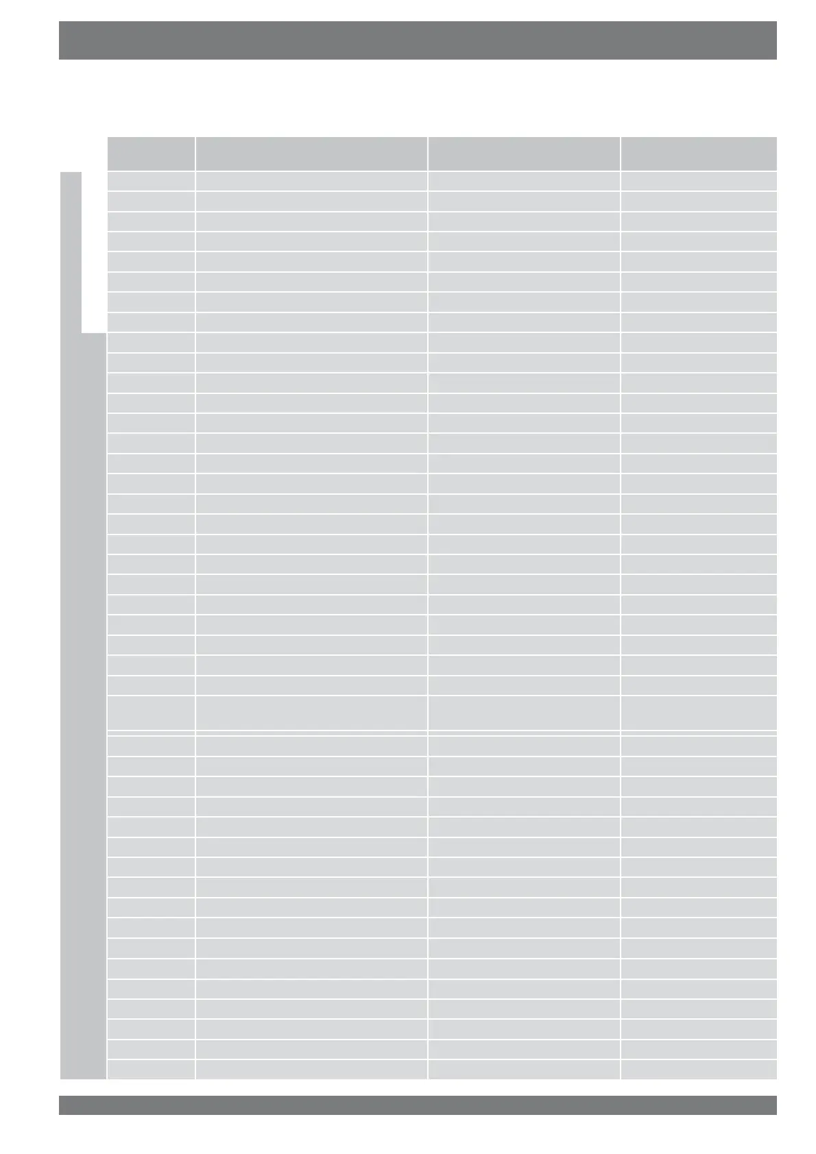
4.2.4 Setting range and factory setting parameters
User
Adjustable
parameter
Description Setting range Factory setting
installer
U 1 9ROXPHVHWWLQJ 50..(max. -10) 100
U 2 9ROXPHVHWWLQJ 50..(max. -5) 150 CWL-300/ 200 CWL-400
U 3 9ROXPHVHWWLQJ 50..300 CWL-300/ 50..400 CWL-400 225 CWL-300/ 300 CWL-400
U 4 Minimum atmospheric temperature bypass 5..20 10
U 5 Minimum indoor temperature bypass 18..30 22
U 6 Target temperature postheater 0..30 0
U 7 Modus proportional inputs A,b,C,d A
U 8 N.a. 0.1 0 (off)
I 1 Fixed imbalance -100..+100 0
I 2 No contact step 0,1,2,3 1
I 3 N.a. 2,3 2
I 4 Switch setting 1 0,1,2,3 1
I 5 Switch setting 2 0,1,2,3 2
I 6 Switch setting 3 0,1,2,3 3
I 7 Imbalance permissible 0.1 1 (Yes)
I 8 Bypass mode 0.1, 2 1
I 9 Hysteresis indoor temperature bypass 0..5 2
I 10 Constant pressure switched off 0.1 0 (no)
I 11 Preheater or postheater 0, 1, 2, 3 0
I 12 Offset temperature preheater -30 ...+30 0,5
I 13 Filter message on/off 1, 0 1 (on)
I 14 Option pcb present 1, 0 0 (no)
I 15
+HDWUHFRYHU\FRQ¿JXUDWLRQ 0.1 0 (+HDWUHFRYHU\)
I 16
Fan off 1,2,3 1 (output fan)
I 17 Repeat time 1 .. 24 24 (hour)
I 18
Min. switch-off time fan(s) 1 .. 240 60 (second)
I 19
Min. switch-off time fans after
VZLWFKLQJRQ9
1 .. 240 1 (second)
P1
,QSXWYROXPHDWLQFLGHQW 0..max 0
P2
2XWSXWYROXPHDWLQFLGHQW 0..max 0
P3 Bedroom correction input fan -100..+100 -20
P4
Bedroom correction output fan -100..+100 -20
P5
Link make contact 1 0,1,2,3,4 0
P6
Input mode make contact 1 0,1,2,3 0
P7
Output mode make contact 1 0,1,2,3 1
P8
Link make contact 2 0,1,2,3,4 0
P9 Input mode make contact 2 0,1,2,3 0
P10
Output mode make contact 2 0,1,2,3 1
P11
7DUJHWYROWDJHSURSRUWLRQDO 0..10 8
P12
0D[LPXPYROWDJHSURSRUWLRQDO 0..10 10
P13
Integration time proportional 1 0..1250 0
P14
7DUJHWYROWDJHSURSRUWLRQDO 0..10 4
P15
0D[LPXPYROWDJHSURSRUWLRQDO 0..10 10
P16
Integration time proportional 2 0..1250 0
P17
/LQNEHGURRPYDOYHV 0.1, 2 0