Heat Recovery unit CWL-300(B) / CWL-400(B) with option PCB 7
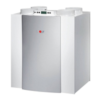
$ PRUH FRPSUHKHQVLYH UHDGRXW SURJUDP LV DYDLODEOH IRU WKH
installer. Pressing keys “F” and “OK” for 3 seconds calls up all
LQVWDOOHUGDWD,QWKLVPHQXWKHYDOXHVcannotEHPRGL¿HG
$FWLYDWLQJWKLVPHQXDOZD\VFDOOVXSVWHSQRVHHWDEOHVHF-
tion 4.2.1); pressing key "+" calls up the installer and user data
and pressing key "-" takes you back to step no. 1.
After 5 minutes this menu automatically disappears and the
display will show the operational situation again.
When an option pcb is mounted, the installer has one additio-
QDO UHDGRXW RSWLRQ FRPSDUHG WR WKH VWDQGDUG YHUVLRQ WKDW LV
step no.16.
,QWKHHYHQWRIDIDXOWWKHIDXOWFRGHDSSHDUVRQWKHGLVSOD\
see also chapter 5
Settings Chapter 4
5497-0
4.1 Reading out settings
4.1.1 Read out settings by the user
4.1.2 Read out settings by the installer
4.1.3 Readout data user / installer
The next page (page 6) contains a table with all step numbers,
with description, for the user as well as the installer.
4.2 Modifying settings
$QXPEHU RI VHWWLQJV FDQ EH PRGL¿HG WR DGDSW WKH DSSOLDQFH
WRWKH VSHFL¿F VLWXDWLRQ$JDLQ DGLVWLQFWLRQ LV PDGHEHWZHHQ
VHWWLQJVWKDWFDQEHPRGL¿HGE\WKHXVHURUE\WKHLQVWDOOHU
4.2.1 Modifying settings by the user
The user can modify a limited number of settings, that is U1 to
U8 inc. (see table section § 4.2.3); how to modify these settings
is shown in the menu structure diagram §6.5 and described in
detail in §6.2 of the installation instructions CWL-300/400.
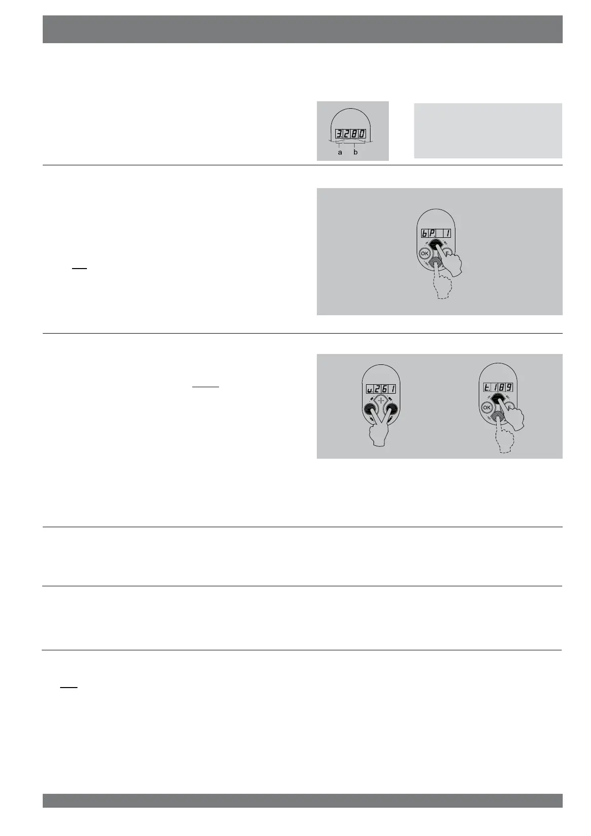
As standard the present position of the multiple switch and the
FRQQHFWHGRXWSXWYROXPHDUHVKRZQ2SHUDWLRQDOPRGH 2Q
the left the position of the multiple switch (position 1, 2 or 3) is
VKRZQDQGWRWKHULJKWRIWKHGRWWKHYROXPHRIWKHRXWSXWIDQ
is shown.
a = Setting multiple switch
E 9ROXPHRXWSXWIDQ
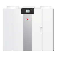
7KHXVHUFDQUHDGRXWRWKHUUHOHYDQWGDWDXVLQJNH\V+” and “-”
(step 0 to step 8). Step numbers are not shown on the display!
See the table of section 4.2.1 for user readout; when no key
is operated for 5 minutes, the display automatically returns to
operational mode. Key “+” can be used to scroll through the
menu; key “-” always takes you back to step 0. Modifying set-
tings is not possible in this situation.
When an option pcb is mounted, the installer has two additional
UHDGRXWRSWLRQFRPSDUHGWRWKHVWDQGDUGYHUVLRQWKDWLVVWHSV
no 7 and 8.
>3s